Wednesday, January 24, 2018

Yet another resurrection..

These are some notes I made regarding a project I am proposing for a local repeater group in an effort to introduce new hams (so-called "Baofeng Techs") into the technical world of radio, electronics, and kit-building. Racking my brain for a simple project that might be of interest, I came up with the circuit below. It is the famous NorCal S1/S9 Signal Generator which was a kit produced by the NorCal QRP club many years ago that has since been discontinued. I am not sure of the licensing or other proprietary ramifications but, considering the time this has been out of production and the "modifications", I am sure this will qualify under the terms of "fair use".

Of course, it is a simple crystal oscillator with the option of switching between four crystals and between two output levels (S1/S9) and used for the purpose of aligning and adjusting the receiver sections of QRP rigs - or any receivers, for that matter. While it will not make immediate sense to Baofeng Techs, it offers the following:

(1) Kit building experience.
(2) Parts identification.
(3) Soldering practice.
(4) Assembly checkout.
(5) Introductory education to crystal oscillators.
(6) An end product of use in checking/aligning a receiver.

Herewith is the original schematic:


The original kit used SMT parts but I will not do so for this one for obvious reasons. Through-hole parts are easier to work with for beginners and I can source most of them from my junk box. But I do propose to create a PCB to simplify the build. The art here will be to generate the PCB and I hope to do so by following int he footsteps of Chuck Adams, K7QO, who is leading his doughty band of QRPers over at QRP-Tech on the groups.io email list. Chuck has found a few Chinese board houses who will generate PCBs for a shockingly low fee provided you send them the Gerber files. He has done this with the 25th anniversary build of Wayne Burdick's NorCal 40A transceiver, his Colpitt's Oscillator Crystal Checker circuit (see my earlier "Looking for a Perfect Match" post), and the revival of Wayne McFee's PTO-tuned TinEar Receiver.

I have most of the parts (including crystals) on hand but the financial killer will be the four-position switch. So I propose to cut this down to two crystals because the DPDT switches abound and the sockets made from the pin header strips that can be cut off as desired.

Anyway, that said, I will need to come up to speed in a PCB circuit design software that will generate Gerber files so the boards can be duplicated. After that, it becomes a matter of "packaging" the kit and for that, I will probably use the same concept I did when I mounted my K7QO crystal checker circuit:


It is merely a sample wood flooring chip I obtained from Home Depot which are variously free or ransomed off at a quarter of a dollar per chip. These can have the ugly tangs sawn away and they make perfectly marvelous bases for a project. Add the copper clad front and ground plane and you are retired in Florida, Wyatt!


Project Postscript Notes
I will do this project because I'd like to learn PCB fabrication and the related software. However, this effort was lost in the fog insofar as the local repeater association members are concerned. They seem content to bide their time on VHF and prattle back an forth -- which is O.K., I guess. I mean, to each his (or her) own. So this will herald a serious disinvestment of my time and effort with those who do not wish to learn. As someone once said, don't try to teach a pig to sing because it's a waste of your time and in annoys the pig.

Tuesday, January 16, 2018

Closing Loops

A while back, I walked picked up a couple of deals at the Pomona swap meet -- a Heathkit HG-18 sine and square wave generator that looked like it was fire-bombed and an AN/URM-25D signal generator that also looked like it was at death's door. The HG-18 was preliminarily inspected and posted here and the AN/URM-25D here. I wanted to close the loop on these, so here goes.

Actually, you don't "pick up" an AN/URN-25D at a swap. They're magnetic and..well, as I explained to the folks on the Antique Radio Forum:


Anyway, these things are not nearly as bad as they look. Military gear is virtually hermetically sealed and the innards are usually pristine. I used to collect military radio gear and some of the World War II and Korean War stuff -- particularly that which was to serve in tropical environments were water and fungus-proofed to beat the band. So, you can imagine how clean the insides of test equipment that dwelt in a service shop must have been babied was like.

Bottom line on this was that there was a cold solder joint on the frequency turret and, once repaired, the little beast was dead bang on. All that was left to do was get out the can of elbow grease and get 'er done.


..rock solid stable as well. Not bad for some old gal you pick up at a swap meet, eh?

Thursday, January 11, 2018

Proposed Winter Field Day Site

This is at Mile Square Park in Fountain Valley. Looks a lot gloomier than it really is. This is in the midst of Winter after two days of rain took down a lot of leaves. This is a large park bounded by Warner Avenue on the South, Brookhurst Avenue on the west, Euclid Avenue on the East, and McFadden Avenue on thr North. It's one mile by one mile ~~ hence the name Mile Square Park. (Stultifyingly obvious.)

Dick, WB6JDH, and I wandered over there yesterday to snap some shots of a prime location within a short walk from my QTH. While there are a lot of trees -- many very high oak or eucalyptus -- there is this one spot bounding what is called "The Glen" that features a very promising stand of trees for antennas.

The shots below are rather gloomy and stark but this was on a cold day after two days of rain and a lot of clouds. With any kind of sun, the site is much more pleasant with an abundance of benches and an oft-disregarded sign advising against the intake of spirits. (This can be circumvented with the judicious use of brown paper bags should one desire a can of suds with his or her tuna sandwich.)

If the hike in is too much, there is parking very close by this spot. Also, apres contest (around 1600L), there is a nice commodious pizza joint a half mile down the road.


Map of park showing "The Grove" location circled in red.

Prime spot with stand of trees in "The Grove"
Looking into "The Grove"

Benches near the prime stand of trees in "The Grove".

These be the trees..certainly big enough for decent antennae.

Dick accosting a squirrel.

More squirrel action with Dick playing hard-to-get.

Some other trees.

Pond across the street.

Benches near the prime spot. Note proximity of parking in background.

More benches.

Disregard; just bring brown paper bags.

Pond across the street.

Additional sites across the street. Typical of locations throughout the park.

Monday, January 1, 2018

Looking for the perfect match..

After a delay for the holidays and my son coming into town from his USAF training at Sheppard AFB in Wichita Falls, Texas, I am finally resuming the NorCal 40A Anniversary project started by Chuck Adams, K7QO. This little juncture covers the crystal matching phase of the effort. And, typical of me, it's a start-to-prepare-begin-to-plan-to-organize-to-commence affair where I divide the two piles of crystals I got off of eBay into matched sets of six for the radios I am contemplating. (I will be assembling a 40-meter and 30-meter version; more about that later.)

This was using Chuck's crystal checker circuit I ordered from ALLPCB.COM but he got curmudgeonly and revoked his old website and the videos so, while there are other crystal checker circuits available, the principle shown here is the same.

Anyway, I am not exactly satisfied with the results returned with the first two of Chuck's I built and want to determine how to optimize or augment the circuit. If nothing else, you can build up other circuits with different crystal values and use them as sources of RF. But be advised that the Colpitt's oscillator -- at least this design -- has problems oscillating above 15 MHz.

Also, Chuck's thought was to use this connected to a Morse code frequency enunciator to determine a crystal's frequency. As each is measured, it is sorted -- matched -- with other crystals of similar frequencies. This is essential to determine the band pass frequency of the filter and the BFO of the radio we are building. From Chuck's process, I used a frequency counter and matched mine to the nearest 10 Hz. I made a "grid" to help facilitate this matching process using Excel. 

Note that the gross frequency for a batch was determined by measuring about 10 or 15 of them and generating the grid of one kilohertz spread by 10 Hz increments as Chuck did.

The sheet is laid over some 8x11 Styrofoam I have and as crystals are measured, they are "punched" into the appropriate slot. However, as I started measuring the crystals, I noted that the frequencies tended to drift (mostly upwards) and it was not convenient to determine the actual frequency. At first, I thought about experimenting with a higher value for R0 as Chuck mentions in the first video but, not wanting to go any further down the rabbit hole, I opted for the "just get 'er done" philosophy and opted for a "timed measurement" by letting the crystal "cook" for approximately 15 seconds to determine the frequency. Besides, I had just scored a couple of really, really neat stop watches manufactured in the USSR in the late eighties -- byproducts of the Soviet space program -- and thought it neat to put them to work.

Also, I felt a little more comfortable using a frequency counter instead of the CW enunciator. So, below is the setup halfway through my measuring/matching the 4.9152 MHz batch I got for the 40 meter version:


The stop watch was just started and a crystal inserted and, after 15-20 seconds whizzed by, the crystal was "posted" to the Styrofoam in the correct slot. The stop watch just kept running so I could approximate the 15-20 seconds; better than reading the tiny second hand on my wristwatch and around 15 seconds was adequate for a crystal to stabilize.

This made fairly quick work of a pile of these little beauties but it was interesting to note that the 8.000 MHz crystals were more "spread out" than the 4.9152 MHz crystals.

4.9152 MHz Initial Batch

4.9152 MHz "Overflow" Batch

8.000 MHz Batch

  While the 4.9152 MHz batch will not be hard to gather into six crystal groups, the 8.000 MHz batch will be a little problematic because of their distribution. But that's for another day.

Wednesday, November 22, 2017

Let's go to the video..

Chuck, K7QO, has posted some videos on his QRP Tech NorCal40A project on YouTube and I have relocated those published as of this date here. They are similar to his 1-Watter series except a little quicker on the up-take. That is, there isn't a lot of hand-holding. You either get it or you don't. I have added them here (and will try to add new ones as they are published).

UPDATE: about several months ago, it seems that Chuck got pissed off at the ham radio world and stormed off taking his ball and jacks with him. So the videos are gone-zola! So sorry that's the case because these were terrific videos and reflected Chuck's pristine craftsmanship.

But, long before he did, I downloaded them all and now possess them in a secret vault I have in my fortified hideout!


Bwaaaaaaahahahahahaha!

Whatevs.  Eat your heart out, Chuckles!

Monday, November 20, 2017

Resurrection..or just waking up?

After what may seem like an interminable slumber and having just retired from a career of software development, I am now enjoying the fruits of my labors. (For the record, this is different than when Herb Caen famously observed that the owner of Finocchio's, where female impersonators were the staple act, lived "off the labors of his fruits".) In any event, I land upon these sandy shores with a healthy list of projects and opportunities to push out my wonderful experiences in electronics and QRP. What lays before me are hopefully idyllic days of building, soldering, testing and operating.

Note to visitors: I shall close the loop on the ARN/UM-25D cleanup (done many moons ago) and the wrap-up of the One-Watter series later. In the mean time, herewith is a post re the nascent project being started by Chuck Adams and the QRP-Tech folks (citations hereinafter) are doing to honor the 25th anniversary of Wayne Burdick's NorCal 40A QRP rig. These are preliminary shots for the benefit of my bud, WB6JDH, who will join me and others in scrounging and building these beasts. Our aim will be to do an "SnS" (Scrounger and Solder) of the 30 meter version of this as outlined by W0CH (main page here and 30-meter version here.)

Here are the pics of the QRP-Tech boards and my original TRW Swap Meet NorCal 40A find as a reference and for Dick to survey:

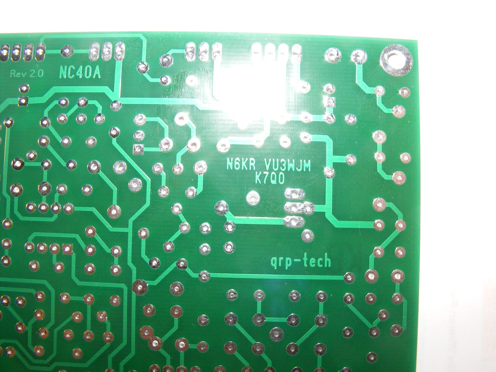
Top of QRP-Tech Board

Bottom of QRP-Tech Board (Flipped to Right)

Close-up of Q7A area

Close-up of Q7A Area

Small Pinholes?

More Small Pinholes?

Original Wilderness Radio NorCal 40 Front View

Original Wilderness Radio NorCal 40

Original Wilderness Radio NorCal 40

Original Wilderness Radio NorCal 40

Original Wilderness Radio NorCal 40

Original Wilderness Radio NorCal 40

Original Wilderness Radio NorCal 40

Thursday, December 8, 2016

..same for the old/new AN/URM-25D

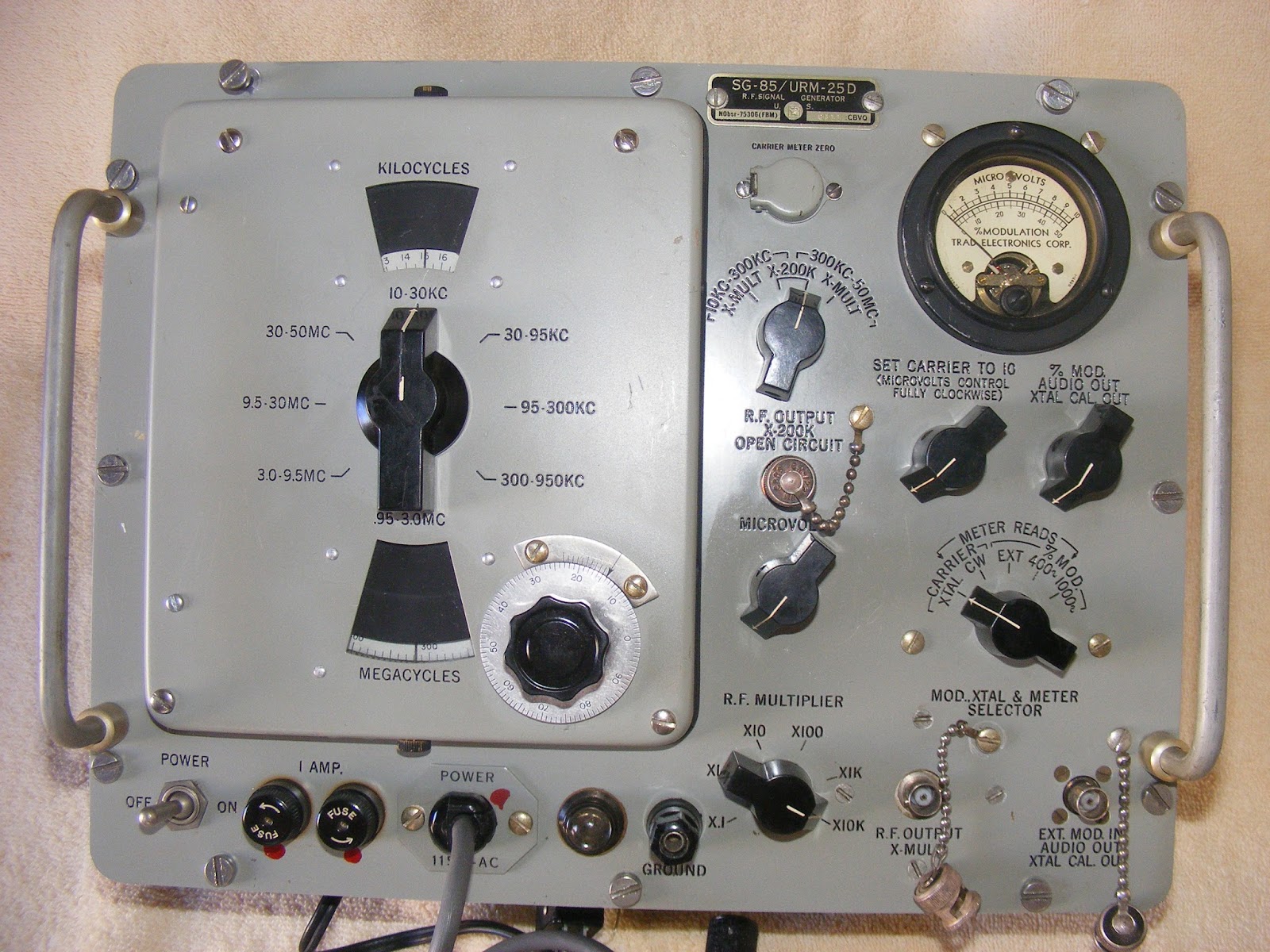
As with the IG-18 in the previous post, I scored an AN/URM-25D that looked like warmed-over dog shit outside but turned out to be very promising inside. Actually, when I stuck it on the bench and checked it out just after the swap meet, it was dead on and rock stable. Aside from the cosmetics, the dial lights were burnt out and one of the bands was intermittent.

Here's the "before" pictures:


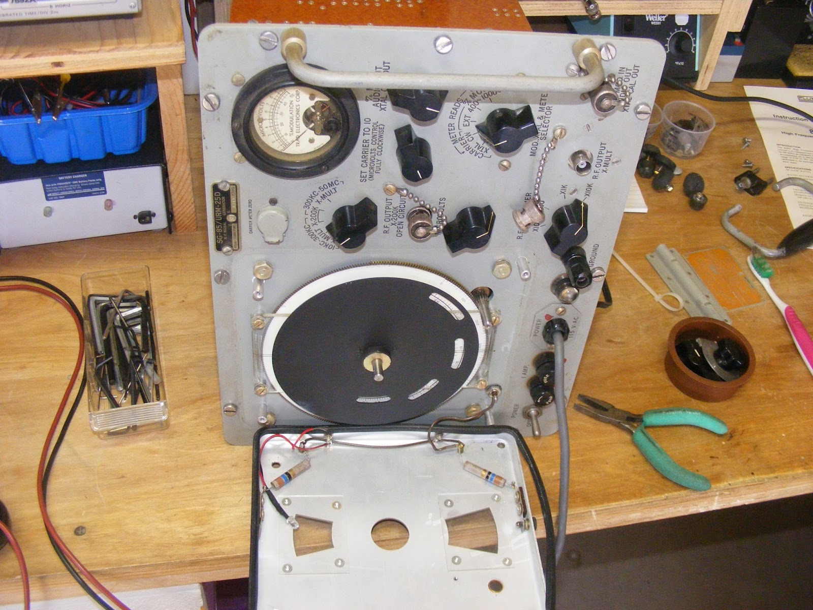
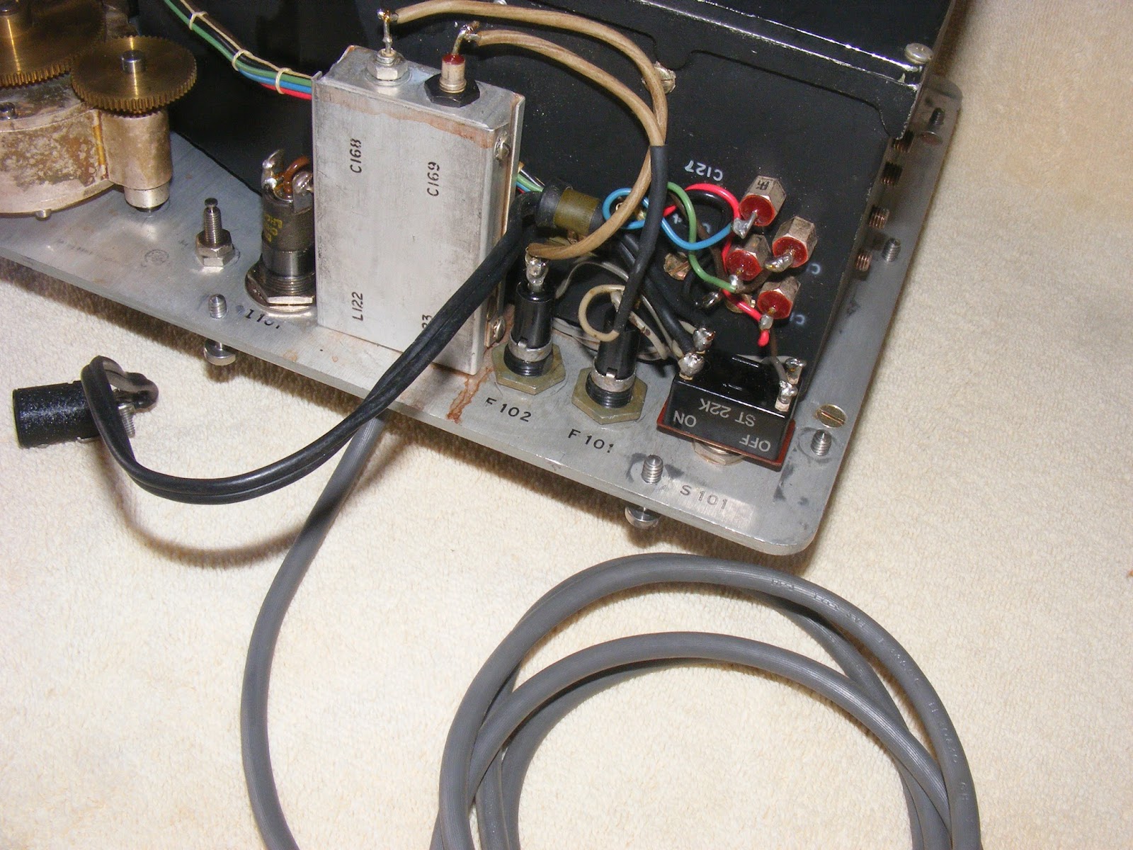
..replaced the lights and related circuit with some bright LEDs but am less than happy with their brilliance - but they'll do. As for the intermittent band, I disassembled the unit and started poking and prodding but could not find anything amiss with the circuit. In the procees of doing that, however, I lifted the legs on a couple of components so the could be checked. When they were re-soldered, the band seemed to function correctly. SO, I saw no reason to go further.

Here are the "during" pictures:


Afterwards, I gave it a good cleaning, repainted the case, and put it back together. Will add they "after" pictures when I get a chance.