Friday, December 20, 2019

Simply Half-Wave Trapped Antennas Addendum 1 - Nice to Have Stuff

Paul Carlson in a small part of his lab
This is a short rant about [electronic] tools and what you should anticipate arming yourself with.

If you are new to ham radio and foresee getting into serious tinkering, First get yourself a DMM (Digital Multimeter).

Period.

These range from literally free (with a coupon from Harbor Freight Tools) to a Fluke (or higher grade instrument) that will cost you almost a thousand buckos. Scout YouTube for some reviews but cease once your eyes begin to glass over. Guys like Dave, the histrionic Aussie host of the EEVBLOG series, will have you believing you cannot survive without owning a Fluke meter that can withstand being thrown off a skyscraper. M. J. Lortin, the laconic Englishman, will have you sound asleep five minutes into part one of an hour long video of which there are two additional parts.

Other guys will show you anywhere from three to ten DMMs they bought just so they can do a review of the infinitesimally subtle differences between each. Trust me, if you get a decent one for about $15-50 with auto-ranging and a few other features you might want, you will be fine. Also, trust me: it will not be the last one you own.

O.K., that covers DMMs and we'll leave oscilloscopes for later. But, when you get one, you will be surprised how you did without it.

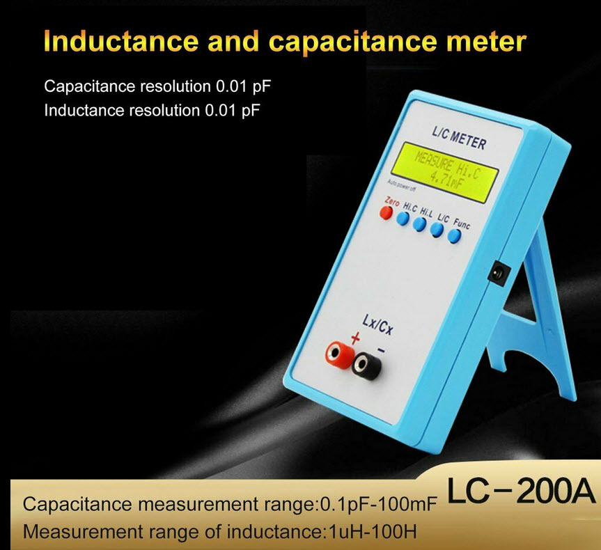
I would only add -- for the moment -- that you make a modest investment into three items that will save you a lot of headaches, guesswork, and make this corner of antenna and radio building a lot of fun. These are a component checker, an LC meter, and an antenna analyzer. Examples of these are shown below but are not exact product recommendations. They are part of the bounty of cheap Chinese stuff exported and sold on eBay for a reasonable price. Recommendations can be sought amongst friends and on VHF/UHF technical nets and round tables. Wise shopping will set you back from $20-100 tops.


Component checkers are surprisingly good at telling you a lot about each little doodad you hoover up at swap meets from transistors to inductors and including resistors, capacitors, diodes, and other stuff. They might even be good enough to tell you about the inductors and capacitors you are using for your traps. They are around $15-25 on eBay.
LC meters are higher quality gadgets that give you a more accurate reading of the inductors and capacitors. If your component checker is crappy, then consider one of these. They are a little more than $20 on eBay.
Antenna analyzers range from cheap to literally a kilobuck (or more). If you pick up one for HF only (1-60 MHz), expect to pay around $50-80 for a low end one. I have a couple I picked up in that price range and am perfectly content with what they show me and don't need curves of graphs drawn.
But, trust me, you start tinkering and you will always see "something better" and end up having about three or four items that essentially do the same thing. Of late, there is a "NanoVNA" on eBay that sells for about $60 and will actually draw curves of your "network" (the trap). If it is sexy enough to compel you to open your wallet, knock yourself out.

If you want to go old school, you might consider picking up something called a Grid Dip Meter or "GDO" (Grid Dip Oscillator). Back in the day (the 1950s onward), these were considered the "Swiss Army Knife" of test instruments as they could be used to test LC tank circuits, antenna resonance, and even serve as a signal generator. Here, Alan Wolke, W2AEW, does a nice video on how these can be used.


When my dad passed away back in 1992, I inherited his Millen 90651A which, at the time, was considered the Cadillac of GDOs. I developed a "jones" for these and over the course of time owned a number. The collection dwindled but I kept my dad's and the cream of the crop and still use them quite a bit, to wit:


The Heathkit transistorized version of this -- like the one in Alan's video -- is worthwhile and is as near as good as the Millen. The Millens and the Heathkits are not worth owning if they are in questionable condition or do not have the coils with them. Most of the time, the ones offered on eBay are dog meat and way overpriced at that. Occasionally, one will come along and is worth nabbing. Even better is picking up one at a swap meet or ham fest.

Alan produces some outstanding technical videos and they are well worth watching. His work is thorough, explanations are straightforward, and he publishes those magnificent notes he makes for download from a link on each video.

Another simple "old-school" tool is the noise bridge. These are simple circuits that generate white noise. As explained by an Australian, Ralph Klimek in a 1995 article on his website:
A noise bridge is an impedance measuring device that can measure real and imaginary components of complex impedance at RF frequencies. It uses a radio receiver as a detection device and a broadband noise source as the excitation source for the bridge. This eliminates the need for a precision signal generator notwithstanding the fact that the average signal generator does not have sufficient output amplitude to excite and bridge and simple detector. A radio receiver is an excellent detector being sensitive down to microvolt signals and low bandwidth. The noise bridge is an excellent antenna tuning instrument because it gives a rapid and precision measurement and also the noise power induced into the antenna is very small and will not cause interference to others.

Basically, is is an even cheaper version of an antenna analyzer and, if mastered, can be quite useful.
There are "commercial" products available like the venerable Palomar Engineers version or an old Heathkit, and an MFJ unit that turn up from time to time on eBay priced from around $20 on up. I would not, however, pay more than $40 for one. These are shown below:


There is a kit available from QRPGuys for about $20 plus shipping. It works identically to the units above but the advantage is that you get the experience of building it and there is a comprehensive assembly manual here and an "operations manual" here.


Like the GDO above, if you see a noise bridge at a swap meet or ham fest for a reasonable price, pick it up and learn to use it. Anyone can drive one of those idiot-proof antenna analyzers but it takes going old-school to really understand the underlying electronics and antenna theory.

By the way, Paul Carlson is one of the more impressive techs on YouTube. His lab (a smidge of which is shown in the picture above) is truly expansive and, given that he is prone to radios and equipment built in the 50s and 60s, borders on the Gothic. Don't let this put you off. The man is a genius -- both in the literal sense and as a statement of my admiration for him. His YouTube channel is a treasure trove. Here is the intro.

Zuni Practice - Winter Field Day 2020..

A small contingent of the The Zuni MEF will be doing Winter FD but not as a contest, rather a one day antenna and rig "burn in".


As part of that, I will be assembling both a 40m/20m trap dipole as well as a 40m/20m trap vertical and will have pictures and notes on that in this space.

..see you at the end of January 2020.


Tuesday, December 17, 2019

Simply Half-Wave Trapped Antennas Part 3 - Constructing Traps

Constructing Traps
It goes without saying that almost anything can be used as a coil form for the inductor in a trap from air to iron. Classic traps in the days of yore was one made out of the Air Dux™ coil stock (shown below) where one sawed off a hunk for the correct inductance.


Of course, wood dowels, PVC, pill or other plastic bottles -- even card board tubes -- can be used. Take, for instance, this trap made out of a toilet paper tube, a hunk of wire, and a couple of 27 pF silver mica capacitors in series. Obviously, it will not stand up to a cat 5 hurricane -- or even a moderate drizzle -- but it can be "hardened" and weather-proofed and/or hidden in an attic where it will serve duty. (I Would not run more than 100 watts through it unless you have your track shoes on and your homeowner's insurance paid up.)


Also, there's no law that says you have to have a round coil either. A piece of wood with a square profile would work just fine. The take-away here is to use your imagination and see what you have on hand. My preferred material is PVC and generally in 1-inch to 2-inch diameters. The material is rugged, weather-proof, and easy to work with.

Here are a pair of traps I fashioned with some PVC, a 27 pF silver mica cap, some screws, and solder lugs:
The bottom line on constructing traps is the more perusal and experimentation you do, the better your antenna building kills will become. I did a post before this series with a bunch of pictures of traps I built for a vertical antenna. You are invited to peruse those -- as the rest of the blog if you like.

Testing Traps
Once you build your traps you will need to test them; measure their resonant frequencies. I like to measure each component before I assemble the trap and then measure the resonant frequency of the resulting trap. As you will find out, components are not always dead on with respect to their marked value nor are the coils you wind going to exhibit the calculated inductance. Consequently, the resulting resonant frequency will not be what you calculate either. But not to worry. All you need to do is get things "close enough for government work".

First, let me digress and recommend you take a quick gander at this as a hint on tools you should be considering if you would like to progress further away from being an appliance operator.

All of that said about the "nice-to-own" tools, here's some notes and comments on ways to measure the resonant frequencies of your traps. First up is a video by yet another ham who does a great series on how-to projects, Peter Parker, VK3YE. It pretty much describes a way to use your radio and a broadband antenna (i.e., a long length of wire) to roughly determine the traps. It is fairly self-explanatory, illustrates a "cheap method" of doing this since you already have your HF radio, and it follows through with how Peter calculated the values necessary to achieve resonance at the desired frequency. Finally, he shows the resulting traps which -- along with my pictures and pictures of other traps on the internet -- should give you soem good ideas how to fabricate yours.


Unfortunately, he flashes by a piece of information from W8KI's website on traps that speaks to the desirability of component traps versus coaxial traps:

- Trap loss greatly exaggerated by advertising hype
- Traps should not be resonant at the actual planned operating frequency
- Coaxial traps are more lossy than articles conclude
- Coaxial stubs used as capacitors cannot be calculated using pF/foot unless the stub is a very small - fraction of a wavelength long
- Coaxial stubs have a low Q (are relatively lossy) compared to normal lumped components

The actual website is here and it is definitely worth a glance as he develops this theme with calculations. The bottom line is that you don't sacrifice anything by building traps with discreet components versus pieces of coax, the busy-body naggers notwithstanding.

In the link above where I made the recommendations as to the inexpensive test equipment you should avail yourselves of, I mentioned an RX noise bridge. These can be used in conjunction with the receiver on your HF rig to measure the resonant frequency and a good explanation on how to build one as well as use it can be found here. Note that the noise bridge will substitute for Peter's broadband antenna and provide you the antenna radiation resistance as well as the inductive or capacitive reactance.

There is a great article on an antenna noise bridge detector here.

..and another one here.


By this time you should have a couple of traps resonant just below the highest band of your dual-band antenna. (That is, around 13.5 MHz for a 20m/40m antenna.) Next we'll take up building the antenna itself. But rest assured, the toughest part of the job is done.

Simply Half-Wave Trapped Antennas Part 2 - Calculating Trap Values

Antenna "traps" are nothing more than parallel LC (inductor/capacitor) circuits -- also called "tank" circuits. The derivation of "tank" and "trap" is intuitive once one understands how a parallel resonant circuit works or, more specifically, the nature of LC circuits.

There is a great discussion of these on Wikipedia and other renditions abound all over the internet.

But, basically, the take away on these is that -- at a circuit's resonant frequency -- the impedance of the series LC circuit is zero and the parallel LC circuit is [almost] infinite. Leaving the series LC circuit, the parallel resonant circuit's high impedance is due to the interaction between the capacitor[s] and inductor[s] in the circuit. I stole this image from the Wikipedia article but it shows this graphically:


Again, borrowing from the article, this animated diagram showing the operation of a tuned circuit (LC circuit). The capacitor C stores energy in its electric field E and the inductor L stores energy in its magnetic field B (green). The animation shows the circuit at progressive points in the oscillation. The oscillations are slowed down; in an actual tuned circuit the charge may oscillate back and forth thousands to billions of times per second.

Gradually without replenishment, this activity will dissipate. However, with an oscillating power source like energy from your transmitter or received at your antenna, the activity will continue uninterrupted by accepting the energy into the "tank" and or "trapping" it and not letting it pass further - hence the high impedance. (I am beginning to skate on thin ice here and suggest you seek hard tech info elsewhere before this erupts into a fount of formulas.)

The steps to build a trap are as follows:

(1) Determine the resonant frequency of your trap.
(2) Calculate the capacitance and inductance values.
(3) Calculate the number of turns for your inductor.
(4) Construct the trap.
(5) Measure the resulting resonant frequency.

We'll cover steps #1 through #3 here and take up #4 and #5 in the subsequent post on building and measuring the traps.

For the moment, let's assume we're building a 40m/20m trap dipole. (For the sake of this whole series, we are talking about a two-band antenna. I will comment on constructing three or more band trap antennas in the building segment.)

Determine Resonant Frequency of the Trap
The resonant frequency of the trap should be a shade under the starting frequency of the higher frequency band you are designing, in this case 20m. So we are looking for a trap that is resonant in the range of slightly less than 14 MHz (around 13.5 MHz will be fine) so that it will cut off all frequencies above that frequency and acting like the automatic switch described in the first segment.

Calculate Capacitance and Inductance Values
This is almost arbitrary; you can obtain the same resonant frequency by selecting one LC combination and achieve the same resonant frequency with another difference set of values. Avoiding formulas, there's a nice parallel LC calculator to be found here -- and below, I have used it to demonstrate different values achieving almost the same resonant frequencies.
Note that with the selection of two pairs of components -- 27 pF cap and 5 uH inductor or 14 pF cap and 10 uH inductor -- we have achieved traps with approximately the same resonant frequencies and either one would be suitable. Of course, there are other design niceties to be observed in selecting values of components but that is left for your further study.

Further restrictions are, of course, the availability of the values selected. We can wind inductors (which will be covered below), but capacitors come in discreet values. You can kluge a desired capacitance value by either connecting two or more in series where, like resistors, you are adding the reciprocal of the values) or parallel where you are just adding the values.

The voltage handling capacity of inductors and capacitors need to be considered as well. Since traps are at "the end" of the 20m antenna, they will be at a voltage node and that has to be accounted for. If you are working QRP any decent working voltage or gauge of wire should be fine; you can even construct the inductance (coils) from toroids. However, the kilowatt level is another matter so be very careful. (I will probably do a fourth segment on these considerations.)

Also, I need to pause here and enunciate a prejudice. Research into this subject will show you that hunks of coax can be used to build traps. As you can imagine, coaxial cable has, in effect, capacitance between the shield and center conductor and, as such, can serve both as an inductor or capacitor when wound around a form. The advantage to this that you only need to cut off the appropriate length and build the trap. I chose to keep the components separate so you got a better notion of the LC principles.

Calculate Number of Inductor Turns
Inductors take many forms: single-winding layer, multiple-winding layers, toroidal, etc. For our traps, we are constructing a single layer inductor; I pilfered these formulas from the 1981 ARRL Handbook:

Of course, you can enter this into your calculator laboriously, build a spreadsheet, or just use one of the internet sites to do this:

This covers the first the first three of our five above steps and, since this is somewhat long, we'll leave the rest for the third segment on actually building the traps, measuring the resonant frequency, and building the antenna.

Sunday, December 15, 2019

Simply Half-Wave Trapped Antennas Part 1 - The Basics

I was asked by a fellow ham to make a "how to" tutorial available on trap dipoles. A Power Point summary was suggested but I prefer to do a fuller, more complete explanation and, to that end, I am creating some posts on my blog. It is loosely aimed at the following objectives:

(1) Understanding the principles behind a trap dipole antenna without the concomitant EE degree math.

(2) Fabricating a trap antenna for the constructionally impaired from [mostly] ordinary "household" items.

I will probably break this up into four posts on the blog -- this one on the basics, a subsequent one on trap theory and calculations, a third on building traps, and a final one on putting the whole antenna together.

So let's charge right into it, shall we?

A trap [half-wave] dipole antenna is a device that will be resonant on two or more bands by means of one or more pairs of parallel resonant LC "tank circuits". Such a circuit is an inductance and a capacitance hooked together in parallel that exhibits the property of presenting an infinite -- or almost infinite impedance -- at its resonant frequencies.

But let's back up a minute and refresh our memories of dipole antennas. Sparing you the 1,000 words, here's a picture:


If you need a refresher on the derivation of the half-wave antenna formula, you can go here which I heartily recommend doing as it even has a video explanation of dipole antennas. Also, you will see that these antennas are fed with 72-ohm coaxial cable in the literature but, fret not, your 50-ohm coax will be fine for the moment. (But, down the road, you will come to realize that the RF loss of even the best coax is a mega-bummer if you like QRP.)

So, for the sake of argument, we would like to have a half-wave dipole for 40 meters. Hence:


Also, we wish to have a half-wave dipole for 20 meters. similarly:


And, while half-wave dipole antenna calculators abound on the internet, the above was derived from a site put up by West Mountain Radio who also went ahead and published the computations for all of the amateur HF bands, below.


So, armed with these, see that a 40 meter antenna is roughly twice as long as a 20 meter antenna and that we could probably use one antenna on both bands or actually terminate our coax into an antenna with BOTH 40m and 20m elements. And, while there is nothing wrong with either solution, there are drawbacks to each approach. (There are, in fact, problems with trap dipole antennas as well. Hey, nobody's perfect!)

Using the 20m band on both 20m and 40m will cause mismatch problems and compromise the efficiency of the 40m operation a great deal. Conversely, using a 40m antenna on 20m does not work out so well on 20m as it isn't a resonant match on that band. Still in all, it works far better than using the 20m antenna for 40m.

But I prattle.

The other alternative -- feeding a 20m and 40m dipole form one coax -- is called a "fan dipole" (for obvious reasons) and actually is better than a trap dipole but may have resonance or deployment problems. For example the multi-band fan dipole shown below is a stone bitch to deploy and tune without getting all of the bands set up so they don't "de-tune" adjacent bands.


In fact, I live in "CC&R hell" and cannot have the tri-band Yagi on the 70 foot tower we all lust after so a fan dipole in the attic had to do. Fortunately, I was able to lay it out so 40m, 30m, 20m, and 10m played nicely off of one coax but some re-arrangement was necessary. However, in the sense that one coax line and one run of wire can be deployed meets our needs most easily, then the question arises as to how this can be accomplished.

We could, of course, put up a run of 66 feet -- 33 feet on a side -- and put a switch in the middle of each side. When we wanted to work 20m, we'd just disconnect the extra 16 feet by opening the switch and Bob's your uncle, as the Brits say. Of course, this would become a monumental pain in the ass getting out the ladder or crawling up in the attic each time we wanted to change bands.

So what could we do? What if we had a magic device that would shut off the extra 16 feet when we worked 20m but did not when we worked 40m?

This is where traps come in.

It is a characteristic of a parallel LC circuit that, at resonance, impedance is almost infinite. Not to go into the hairy math in this discussion (it is discussed here), we can see that this is as good as the switch we wished to employ.

For example, if we configured our antenna as shown in the picture below, we would have the single run radiating element we desired and, when we transmitted on 20m the parallel resonant traps would offer an [almost] infinite impedance and the antenna would appear to be electrically resonant on 20m. Of course, the traps would not be resonant and the entire antenna length would eb employed and, hence, resonant on 40m.

(Courtesy of  AA7EE)

There's an added benefit to this as well. The inductor in the traps serve ot electrically add to the length of the antenna so therefore the overall length required for 40m is reduced by about 65 percent.

"Great", you say, "When do we start?"

Well, that's for the next post on building traps.