Saturday, May 19, 2018

Dancing a jig..

The great thing about the NorCal 40A project is the stack of boards I accumulated through misuse of the PCB house's weird website. Having a passel of 'em, I figured the little rig is a great tutorial on building and electronics in general. Also, being the obsessive person I am, I scored Rutledge's Electronics of Radio, the test that Rutledge uses for his Cal Tech class based on the NorCal 40A.


Anyway, it became apparent to me that if I was going to delve into this and slam together variants of this little beast, a means of testing these without tacking on the controls making each project look like some electronic Medusa.

So, as Tim Allen famously said, "I rewired it!"

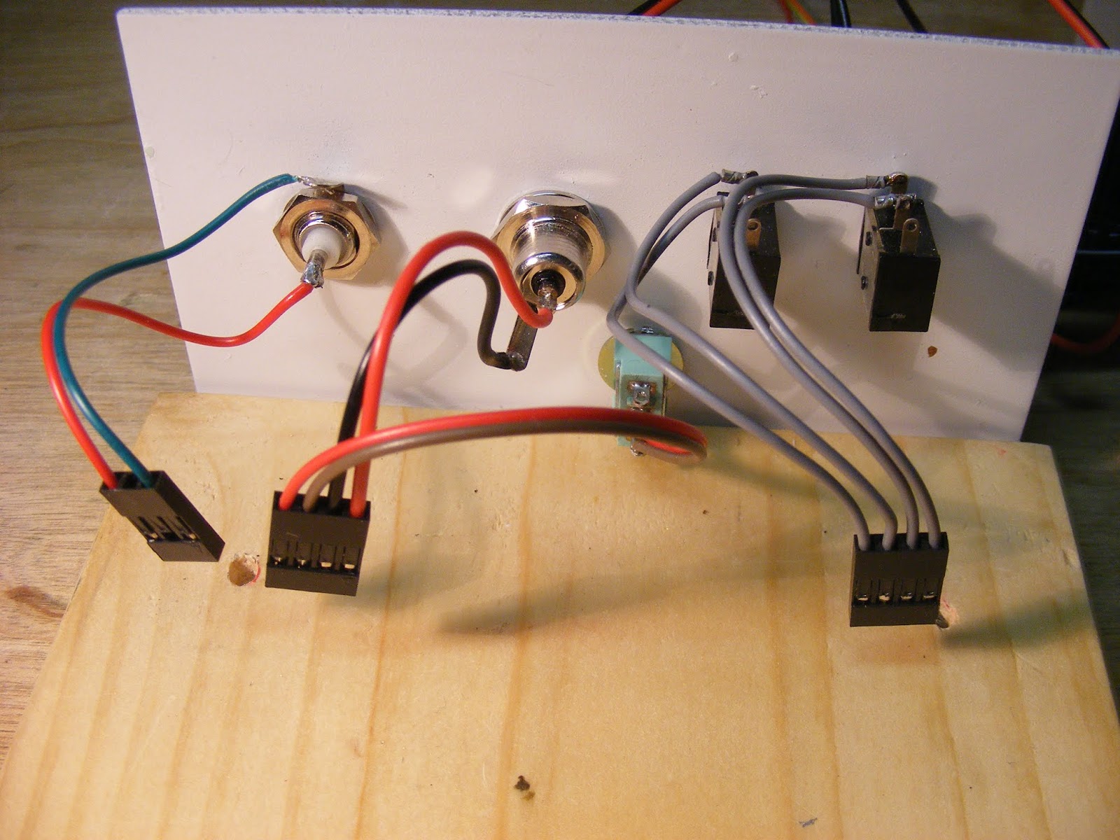
So I built a test jig (introduced in the previous pose below) that would support "plug and play" by incorporating headers and plug/connectors to the controls. (Thanks to Tom, N8TPN, for the lowdown on the connectors that led me to Pololu. A few minutes of browsing there yielded a moderately inexpensive method of implementing the re-usable setup.)

Anyway, the pictures below of my step-by-step construction of a 40 meter version are pretty self-explanatory. If you have questions, leave a comment and I will get back to you.

First, the labelled shots..


..and now the rest.

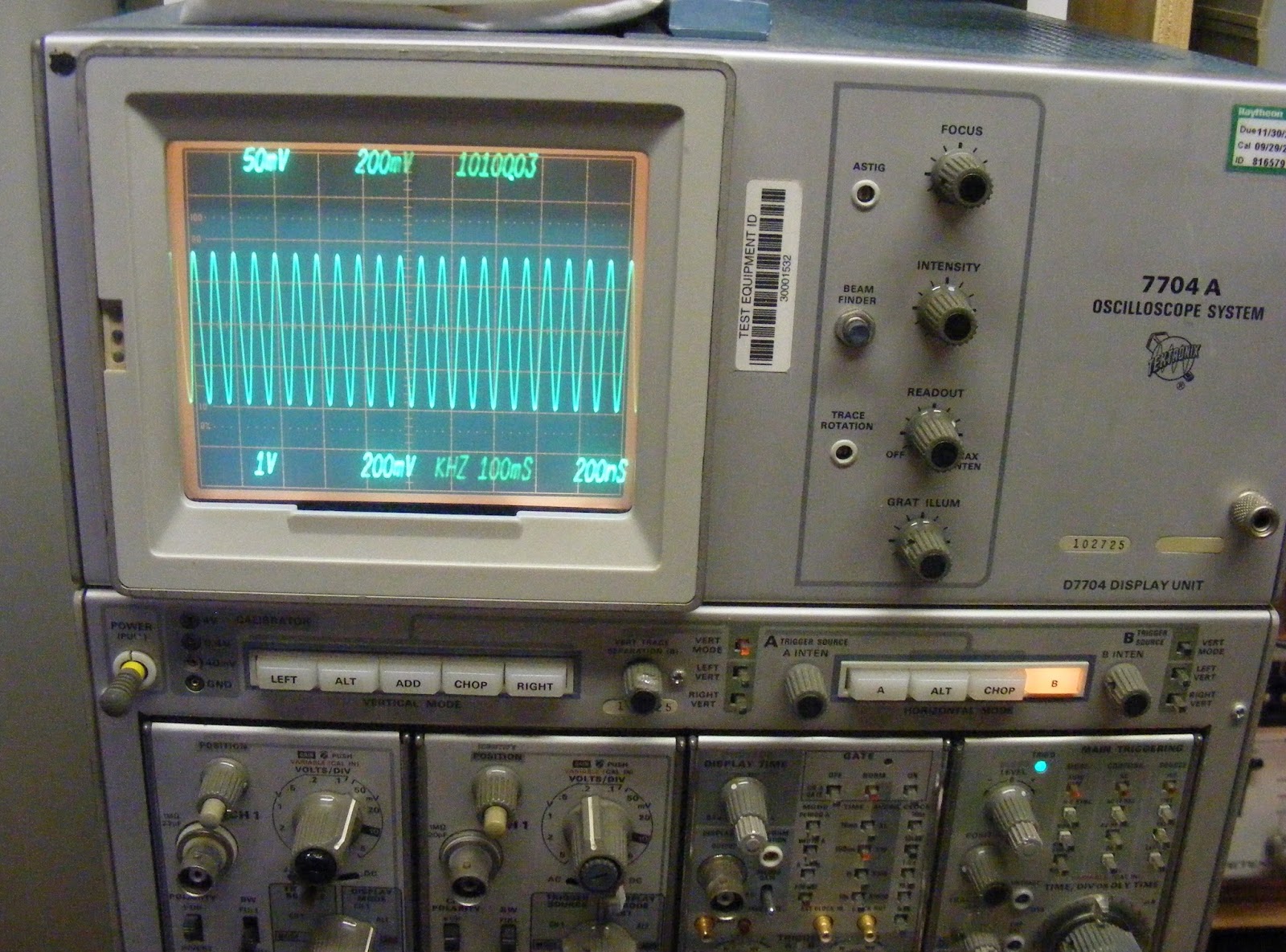
Entire test setup for K7QO's Phase 3 testing.

Add caption


This was one of K7QO's crystal checkers used in generating the 4.915 MHz signal to test the BFO.


And here's a little added bonus. When not in use, the soldering station wand cord used to get in my way and drive me nuts. So, I ran the cord through a used toilet paper tube and use that -- as shown -- as a means of gathering it up neatly.


Tuesday, May 15, 2018

NorCal 80A (80 Meter NorCal 40) and odds and ends..

Did a final checkout on my NorCal 30A the other day and had a chance to preview WB6JDH's 80 meter version shown in the pictures below. The 30 meter version is in my "test jig" that I will be using to check out additional versions being built. These incorporate the header pins and, as such, will be a "plug and play" affair. I still have some bugs to work out but will present a pictorial with construction info in a subsequent post.

Anyway, here are the 30A shots. Top to bottom are the test jig, the rig output, and Dick overseeing the ceremonies.


And here are Dick's 80A shots in no special order.


Monday, May 7, 2018

Offering Tektronix 7D15 Frequency Counter Plug-In..

FORTUNATELY, NO INTEREST WAS EXPRESSED SO I DECIDED TO LIVE WITH THE TWO MINUTE WARM-UP PERIOD AND KEEP THE UNIT AS IT WAS DECENT AND ACCURATE. YOUR LOSS IS MY GAIN.

I have a 7D15 Frequency Counter Plug-In that is spare to my needs and looking for a good home. It is in decent shape with one problem: it requires about 2-3 minutes to warm up and display a frequency. I went through this unit a while ago and could not seem to determine the problem. However, since I have a 7D14 that serves my purposes, I am offering this for $75 plus s&h from 92708 to someone who will make use of it and possibly who may be able to track down the problem.

Typical operation is as follows: I turn on my Tek 7704A and apply a frequency to the appropriate channel and the 7D15 displays "0.00" depending upon the settings. After about three minutes, the frequency will be displayed (accurately) and will change format as the gate time is changed -- per manual spec. Shutting the scope down or removing the unit and replacing it after a 5-10 minute wait will cause the frequency to be displayed correctly. "Cooling down" for about 20-30 minutes will require the aforementioned warm-up period.

Knobs and connectors sound and intact; interior clean; some signs of age but otherwise decent condition (save for the difficulty described). Price includes clean, like-new instruction/service manual with bright pages and no scribbling or underlining as I remember.

Pictures are below.