Thursday, March 26, 2015

Some caveats regarding your HP 403B hunting..

If your eyes are leaking blood, click on the image to enlarge.

Same here..

There was one final anomaly to address before this unit was back at 100% and it had to do with the grounding. When I was done, I buttoned everything back up and started testing but, to my alarm, when the unit was plugged in, the measurements dropped to near zero!

I heaved a great sigh, opened up the manual, and started scratching my head. Where to begin?

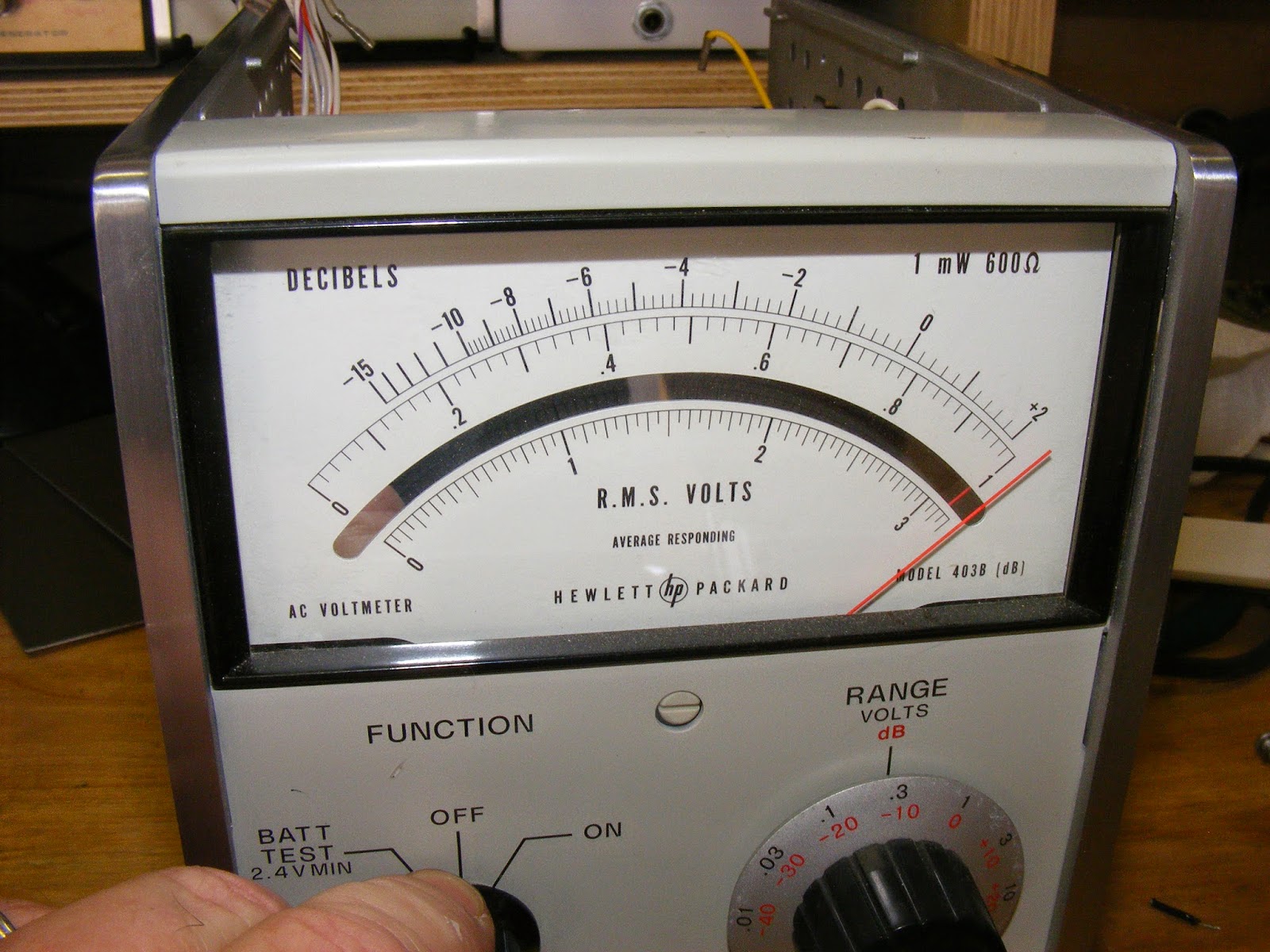
Then I got some advice from one of the hams who was so helpful before. Simply put, there are two grounds on these beasts. One is the chassis ground and the other is the A2 board ground and they usually should not meet. If you look carefully on the schematic (see pictures above), you will see these grounds represented by little triangles with either a "1" or a "2" in them. Obviously the "1" is the chassis ground -- emanating from the power line center conductor and the third plug on the front. (See the picture above where the rightmost ground post has a little triangle with a "1" in it.)

Anyway, hooking up an ohm meter to the A2 ground and the ground post on the front panel confirmed they were a continuous circuit. At the risk of a protracted Agatha Christie session, I gotta tell you that the bottom panel has a strip of foam insulation glued over a bump. My anal-retentive tendencies caused me to scrape that off thinking it was some shock padding or something.

Only after flexing the cabinet and the bottom panel and seeing the ground loop make and break, did I realize that the bump was making contact with the interior ground. So, a quick hit with electrical tape and all was right with the world.

A word to the wise, eh?

Final thoughts: Clearly, these are interesting and useful instruments and -- for the money -- a skillful search will yield a clean and worthwhile piece of test equipment. However, I think I lucked out when I got mine. It was clean, in good shape, and only needed one cap replaced and the battery pack rebuilt. The rest was intact and ready to go.

And now here's a dirty little secret: I got a junker off of eBay for spare parts. The price wasn't much; only about $20 or so plus nominal shipping. So, I guess there's about $80 or so into this unit after you figure all of the parts, batteries, and so on. But as W6GVR said, "Never try to justify a hobby."

Still, if you know what you are looking for -- like so many things in this hobby -- you can pick up a bargain learning from others' efforts and mistakes.

I'd counsel for picking up the cleanest unit you can and, if you can, peer inside and see what you are getting. The junker I got was an absolute disaster; all of the little pins and cables had been replaced by some asshole who must have used an arc welder and acid core solder to complete the wiring. So, if you run across one at a swap, bring along a medium sized Phillips head screwdriver and pop the top and bottom panels (only one screw each), slide them out and take a look. Similarly, the two side panels only require the removal of four screws to peek inside.

If the guy won't let you, run like the wind; he's hiding something.

Also, assume the battery pack is dead. These are thirty years old and NOTHING lives that long except us and turtles and parrots and a couple of bristlecone pines in the upper elevations of the California Sierras.

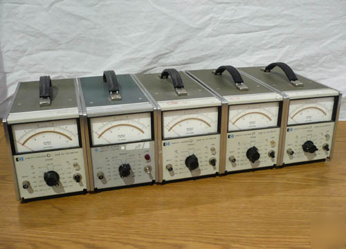
Also note that there are two types of plugs: the more conventional type you see with computers and a wired oval one that are found on the units from the 60s and 70s.


If you're getting one of these off eBay and it has one of those plugs (see picture on right, above) and the seller says it does not include the power cord, again, flee the scene.

I'll put down a few more caveats here as I think of them, but for now, clean and serviceable is usually a good guideline.

-73-


Wednesday, March 25, 2015

Out with the old and in with the new..


After having had a bit of frustration with the shaky needle, I decided to rebuild the battery pack for no other reason than a change of venue, a new adventure, and, what the hell, as my long-ago friend, W6GVR once told me, "Never try to justify a hobby."

Speaking of advice, I received some sterling guidance from yet another ham in Maine, who was in the throes of that awful winter. Herewith is a pretty good description of how the 403B does its stuff:
Howdy Bill--

I watched your flicks! Wow, with the behavior that I witnessed of your 403B it is virtually unusable.

I presume you've got an oscilloscope?

Mine does exactly what yours does on initial power up-- but then settles down and works properly.

On mine switching ranges the needle kicks up a little and then settles down and stabilizes on the reading within about 1/2 second.

I'm working on the house heating system here and that's got full priority-- I've got heat in the house but this is a big job that I'm not enthused about doing this repair but I've got to plod on and get it done.

I want to probe my 403B to watch what goes on at power up -- whether the amplifier(s) oscillate or gyrate at DC levels at initial power up.

I'm also curious what the meter amp does during range switching-- does it oscillate or is it a DC level shift that settles down?

The amp in the 403B may be difficult to probe with the average 'scope unless it's got a 1mV / div vertical sensitivity.

The 403B is designed as a preamp / amplifier or meter driver. It's "native" voltage range is 30 mV full scale-- "straight through". Looks like the preamp has about a 40mV dynamic range. But the meter amp has about a 15 db dynamic range-- or whatever is required to drive the 1ma meter to full scale absolute value. 1 mV into Q3 results in full scale deflection on the meter.

To get to the higher ranges HP engineers have just flanked the preamp (Q1 & Q2) with resistive attenuators. This was done to simplify the input attenuator since it has to work at high resistance. The "secondary" attenuator provides the 1-3-10 scale relation.

The preamp is a bootstrapped emitter follower. The bootstrapping feeds signal in phase from the output back to the input. This makes it look like a much higher resistance input into the preamp since less current drives into the input of the amp.

My schematic shows an 8.2M terminating resistor at the head end into the preamp.

Your meter may vary the resistance as this resistor is selected to provide a termination for the input attenuator and also provide the set meter input resistance. HP chose an emitter follower since they then drive the "intermediate" attenuator which is nothing more than a resistive divider circuit. This way they can use a low "impedance" drive into the attenuator with minimal effect on meter calibration as the user switches through the ranges. This is also done because there is little need for capacitive (or inductive) trimming on the secondary attenuator. The attenuated output from the preamp / input to the meter amp is 1MV full scale (it's probably a tad less than .001V. The emitter follower preamp can not provide any amplification-- it's only function is "impedance" transformation-- HI input to Low output to drive the 'middle' attenuator. You might call the meter driver-- Q3 - Q6 as a voltage to current converter. With .001V input to Q3 the transistor chain will generate 1MA current to drive the meter full scale. To make Q3-Q6 "constant current" a feedback path
across a low value resistor develops. This also linearizes the "steering" diodes especially at low level meter readings (when the needle is just above zero). The voltage drop across the 30 ohm resistor causes the Q3-Q6 network to develop a constant current.

OK-- you say-- so what does all this have to do with the power-up needle dance-- that I dunno yet.

And what about the reading gyrations and the jumps at range selection?

My guess is that the needle fluctuations are because Q1 or Q3 are noisy-- or both are noisy. Q1 is a potential culprit because positive feedback is used and any noise created by Q1 will be exacerbated by the positive feedback from Q2 to Q1.

Another possibility is added resistance by the switch contacts in the "intermediate" attenuator. If you look carefully you'll see that not only is there a voltage divider-- that is tapping "down value" in a resistor chain, but HP has also included series resistors looking into Q3's base. Since the meter amp (Q3-Q6) operate in the 1 mV voltage range (in order to develop 1mA to drive the meter) any added resistance drop will greatly affect the stability of the Q3-Q6 circuit. If the switch contacts are noisy that will also affect the way the meter filter capacitors C17,C18 and the one across the meter behave since those are the "averaging" devices (remember the 403B is only an average reading meter and not true RMS). I think HP recommends cleaning the attenuator switch contacts if the meter jumps around when changing meter ranges.

Kind of the same issue with Q3-- although there's no positive feedback to Q3.

The meter needle not zeroing on the low range-- (.001V) with no signal input and the meter inputs terminated with say a 10K resistor indicates to me that once again Q1 or Q3 is noisy.

You can do a quick test-- by pulling off the "Preamp out" wire (next to the loop gain adj pot). This will still leave Q3's input terminated (not floating)-- see what the meter needle does at any range. Still not zeroing? Switch from the .001V range to the .03V range. Meter zero? If there's no change it points to Q3 being noisy. Another possibility is that C17 and or C18 are leaky. If the transistors are "quiet" they're still going to create some noise level but such that you the observer can not tell that the needle has lifted from zero. But generally the meter will not deflect unless there's an "AC" or better transient signal impressed across C17 and C18. It could be possible that there's a larger than .3V drop across R35. The two diodes are biased almost "on" so that there's no "slack" when an AC signal is present and when the diodes begin to conduct. Although I don't see how this would cause the meter needle to deflect-- unless either of C17 or C18 are leaky.

OK-- I've got to get back to plumbing. I'm sending this as some food for thought.

I have to find some time to experiment with my 403B on this start up needle thing.

73s

Bob
Anyway, back to the battery pack rebuild. You will note, if you do any research on the 403B, that it designed for long-term portable operation and the power supply is nothing more than a charging circuit for the ample batteries that comprise the entire middle compartment. (See the pictures here and in the previous post.) Mine came with four tubular batteries -- each 7 VDC when new and charged -- for a total voltage of 28 volts. These are circuited to deliver variously +/-13 volts and 7 volts to the main A2 board. (There is little else but the supply and the A2 board. See Bob's description above.) Of course, like all good things, these batteries are not readily available so some ingenuity is required to concoct a substitute.

Long story short, I cast about on eBay and discovered some NOS cordless cell phone battery packs at 3.6 volts each. Simple math reveals that eight of these will do nicely and there is not a great shoe-horning effort required to stuff them in the case. Be sure you get NiCD batteries and not NiMH. The charger/power supply will fry the NiMH batteries. Here are some pictures of the old batteries and the replacements:


It was an easy matter to join two of the original 3.6 VDC packages into one 7.2 VDC battery as the pictures show. The trick came in wiring them together to get the correct voltages the original batteries supplied but as long as you carefully disassemble the old pack, remember where the purple/black, red, blue, and striped wires hook up, you should be in good shape. I would say my only disappointment is applying the heat gun with too much vigor to set the shrink tube on the battery wires as it caused the yellow binding plastic of a couple of the packs to melt. See the picture above -- it also gives a decent pictorial on how to wire the packs in.


The diagram above is more a depiction of the battery cell hookup in terms of the old style batteries. Below is more of a schematic diagram in the event you use different cells.


By the way, they are nicely held in place by those little two-sided sticky pads from 3M.

Final note on batteries and the 403B: The battery test position of the unit indicates the battery voltage divided by 10. For example, the manual cautions that the batteries need recharging when the meter reads "2.4 volts" which is, of course, 24 volts. In the picture above, my new batteries charge up in excess of 30 volts and, consequently, read off-scale. They do hold a charge as well. The unit fully charges up in the on position and has held a charge for at least a week now sitting on the shelf. (See picture at top of this post.)

Oh, and the great news about this rebuild: the meter needle is rock stable! So it seems that a dead pack was the problem after all!

Next up: the two-ground problem and some meter idiosyncrasies.

-73-

HP 403B Restoration

..well, that would be a bit of braggadocio on my part because my original eBay unit was in immaculate condition. It just had some problems, that's all. And to say I solved the problems would make me a lying sack of crap. So I will forthwith present videos, pictures, and excerpts of the incredible help received form some fine hams who helped me nurse this thing back to health. Firstly, a couple of "silent videos" I posted on You Tube showing the problems with the unit -- and why I dubbed this "Shimmy Shimmy Shake II".

Here's part I, comparing it to the HP 3400A measuring the same voltage. Note that after the meter "warms up" (this "mambo" is typical of HP AC voltmeters), the 403B continues to wiggle.


Here is part II and the wiggling continues..


The three main concerns about this meter were the wiggling, the wild jumping when the range was switched, and the almost-moribund battery pack. I initially went out to the Yahoo HP group and got the following advice from Chuck Harris, a regular there (emphasis added):
Hi,
Your 403B should achieve a reading in a fraction of a second, and should be rock stable. It should never glitch, jump or waver.
So, you have a few of possible causes:

1) your voltage source is intermittent.
2) your meter is broken.
3) there is a transmitter that is occasionally transmitting nearby.

The 403 is very simple, and doesn't have a lot of possible fault areas. Knowing HP equipment from that vintage quite well, I would say that its problems are likely one of two things:

1) bad electrolytic capacitors
2) dirty switch contacts.

As I recall, the 403 is littered with Sprague TE style axial leaded electrolytic capacitors. They are marked either TE, or The most notable characteristic is the body is bright aluminum color, covered with a sleeve of clear heat shrink tubing. I have found a large number of each style that have gone open circuit...the rubber end seal becomes brittle, and allows the electrolyte to dry up. They can be replaced with any high quality modern axial lead electrolytic. I prefer to use Nichicon, or Panasonic 105C rated capacitors. Pick a long life variety. ESR is not important. Mouser and DigiKey catalogs are littered with suitable replacements. The exact values are not critical (or they wouldn't be aluminum electrolytic capacitors). There exists a tantalum style capacitor in this same appearing case, that has a glass ceramic end piece, that is very reliable, and should be ignored...I don't think there are any in the 403.
Dirty switch contacts should get a drop of Caig DeOxit on the metal contact area, and the switch should be worked around. DO NOT HOSE THE SWITCH DOWN WITH CONTACT CLEANER!
Dirty pots should get a drop of Caig Slider-lube on their contact and element area.
~Chuck Harris
Following Chuck's advice, I checked the ESR of all the caps and the only one found wanting was the huge C20 cap which I replaced with an almost identical value orange Sprague as shown below:


Still the wobbling needle persisted so I poked around and noticed that C7 was not stock (had been changed) and replaced that with an original cap that tested good for ESR. For reference, I excerpted some pages from the manual (available all over the internet) and made a checklist of caps should you want to do a restoration. Also, here's a couple of pages of schematics with all the little buggers highlighted.

"Click to Embiggen"

"Click to embiggen"

"Click to embiggen"

Then I turned my attention to Chuck Harris's (and other's) advice to apply some cleaner to the range switch contacts -- which helped immeasurably. But the needle still had the shakes so I thought a total re-cap job was necessary.

As I prepared for that, for some strange reason I thought I would  first proceed with rebuilding the battery pack. Dunno why. Anyway, I'll lave that as the subject of my next post and drop some pictures in here of the 403B's battery stock battery compartment for reference.


-73-

Playing Ketchup, or, Shimmy Shimmy Shake II

In bragging about this pathetic blog to a couple of my mates, I realized I had not put anything up here since last November. Rectifying this, here's another project that occupied my existence over he last few weeks.

Seems ham radio for me is a series of Jones -- you know, those "gotta haves" or "gotta dos'"? Well, my Test Equipment Jones fed into my VTVM Jones and, somewhere along the line, I fantasized about scoring a Heathkit AC voltmeter. (Hey, sorry for all the drug talk; I am a child of the sixties, after all.) Anyway,  given that I am also an inveterate and compulsive dilettante, my studies led me to reject that as an option and go for what is more of less the Cadillac of the line: the HP AC voltmeters.

I will spare you all the background save to say that there's a shit-pot full of models made in the 60s though the 80s available at local swaps and on eBay for a relative song. But, before you join in the chorus, take care, lest the melody become harsh and abrading.

There are two distinct models that should attract your attention: "the short ones" and "the long ones". I got both and both came with their own trials and tribulations. The former category is occupied ONLY by the HP 3400AB model (photo shown below).

These are a class act and can be had for anywhere from $20 to $250 -- the lower end requiring and the higher end (usually) coming in a working state and usually calibrated. (Caveat: do NTO even consider the HP 3400B; they're in the high three or low four figutres.)  I got two of 'em: one at the TRW swap meet and one off eBay. The former came with the usual swap meet guarantee: "It was working when my uncle's friend's neighbor unplugged it from his work bench back in '03." That's now in the hangar awaiting some new parts. The latter came from a guy in Dallas who said it was working (it was) and was "just out of calibration" (sticker said '93) and allowed for a return if not satisfied. But it was accurate and did work, so I kept it. It's my go-to guy on the bench.

The cool thing about these is that they're real RMS reading voltmeters and they cover a range of  [almost} DC to 10 MHz -- and are good up to 20 MHz in a pinch. Also, they will read RMS voltages the same based on almost any waveform. I'd get into it some more, but you're a ham, you do the studying. Here's a great article on these voltmeters and such nonsense like crest factor, etc.  I'll wait while you take a moment and read it.

..dum..de.dum.de..dum..de..doodle..de..doo..

O.K., you back? Good!

So now let's talk about the shorties: These are as wide as the HP 3400A but are half as deep and cute as a button -- and there's more varieties of these with more options than you can shake a stick at. Below are stock photos of a 400E, 400F, and 400EL. All have their own characteristics (the "L" means the scales are logarithmic versus linear) and these cover [almost] DC to about 1-2 MHz.

Various and sundry of HP's collection..
If you look carefully on the meter face below the "R.M.S. Volts", it says "Average responding" which is voltmeterese for "Close Enough for Government Work". That is, these meters will read perfectly accurately for sine waves but will be skewed for waves with a differing crest factor. (Time to consult that article link provided above.)

Want to test this theory out? Turn on your HP unit and a function generator and throw a 10 KHz sine wave into the meter. Adjust it so it reads, say, one volt RMS. Now switch the function generator to square wave and tell me what happens. Doing the same thing with an HP 3400A will not make the needle flicker. Thus the difference between "true" and "average" responding.

But I digress.

In searching for these meters, I decided that each of the HP 400 series like the ones above offered drawbacks and weren't worth collecting. But then I stumbled onto the HP 403B.

These are small, portable, battery operated AC voltmeters that are widely available, have a simple circuit, and, with a little skill, can be brought back into the land of the living with a modicum of skill.

I found one on eBay that first became a heartbreak and then a pure joy as I solved all of the problems. How I restored this unit will be the subject of one or more subsequent posts. But, it is an instrument that can be put to very good use in tuning up circuits and determining receiver sensitivity.

..so hang in there.

-73-