Wednesday, March 25, 2015

HP 403B Restoration

..well, that would be a bit of braggadocio on my part because my original eBay unit was in immaculate condition. It just had some problems, that's all. And to say I solved the problems would make me a lying sack of crap. So I will forthwith present videos, pictures, and excerpts of the incredible help received form some fine hams who helped me nurse this thing back to health. Firstly, a couple of "silent videos" I posted on You Tube showing the problems with the unit -- and why I dubbed this "Shimmy Shimmy Shake II".

Here's part I, comparing it to the HP 3400A measuring the same voltage. Note that after the meter "warms up" (this "mambo" is typical of HP AC voltmeters), the 403B continues to wiggle.


Here is part II and the wiggling continues..


The three main concerns about this meter were the wiggling, the wild jumping when the range was switched, and the almost-moribund battery pack. I initially went out to the Yahoo HP group and got the following advice from Chuck Harris, a regular there (emphasis added):
Hi,
Your 403B should achieve a reading in a fraction of a second, and should be rock stable. It should never glitch, jump or waver.
So, you have a few of possible causes:

1) your voltage source is intermittent.
2) your meter is broken.
3) there is a transmitter that is occasionally transmitting nearby.

The 403 is very simple, and doesn't have a lot of possible fault areas. Knowing HP equipment from that vintage quite well, I would say that its problems are likely one of two things:

1) bad electrolytic capacitors
2) dirty switch contacts.

As I recall, the 403 is littered with Sprague TE style axial leaded electrolytic capacitors. They are marked either TE, or The most notable characteristic is the body is bright aluminum color, covered with a sleeve of clear heat shrink tubing. I have found a large number of each style that have gone open circuit...the rubber end seal becomes brittle, and allows the electrolyte to dry up. They can be replaced with any high quality modern axial lead electrolytic. I prefer to use Nichicon, or Panasonic 105C rated capacitors. Pick a long life variety. ESR is not important. Mouser and DigiKey catalogs are littered with suitable replacements. The exact values are not critical (or they wouldn't be aluminum electrolytic capacitors). There exists a tantalum style capacitor in this same appearing case, that has a glass ceramic end piece, that is very reliable, and should be ignored...I don't think there are any in the 403.
Dirty switch contacts should get a drop of Caig DeOxit on the metal contact area, and the switch should be worked around. DO NOT HOSE THE SWITCH DOWN WITH CONTACT CLEANER!
Dirty pots should get a drop of Caig Slider-lube on their contact and element area.
~Chuck Harris
Following Chuck's advice, I checked the ESR of all the caps and the only one found wanting was the huge C20 cap which I replaced with an almost identical value orange Sprague as shown below:


Still the wobbling needle persisted so I poked around and noticed that C7 was not stock (had been changed) and replaced that with an original cap that tested good for ESR. For reference, I excerpted some pages from the manual (available all over the internet) and made a checklist of caps should you want to do a restoration. Also, here's a couple of pages of schematics with all the little buggers highlighted.

"Click to Embiggen"

"Click to embiggen"

"Click to embiggen"

Then I turned my attention to Chuck Harris's (and other's) advice to apply some cleaner to the range switch contacts -- which helped immeasurably. But the needle still had the shakes so I thought a total re-cap job was necessary.

As I prepared for that, for some strange reason I thought I would  first proceed with rebuilding the battery pack. Dunno why. Anyway, I'll lave that as the subject of my next post and drop some pictures in here of the 403B's battery stock battery compartment for reference.


-73-

Playing Ketchup, or, Shimmy Shimmy Shake II

In bragging about this pathetic blog to a couple of my mates, I realized I had not put anything up here since last November. Rectifying this, here's another project that occupied my existence over he last few weeks.

Seems ham radio for me is a series of Jones -- you know, those "gotta haves" or "gotta dos'"? Well, my Test Equipment Jones fed into my VTVM Jones and, somewhere along the line, I fantasized about scoring a Heathkit AC voltmeter. (Hey, sorry for all the drug talk; I am a child of the sixties, after all.) Anyway,  given that I am also an inveterate and compulsive dilettante, my studies led me to reject that as an option and go for what is more of less the Cadillac of the line: the HP AC voltmeters.

I will spare you all the background save to say that there's a shit-pot full of models made in the 60s though the 80s available at local swaps and on eBay for a relative song. But, before you join in the chorus, take care, lest the melody become harsh and abrading.

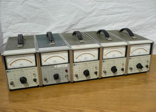
There are two distinct models that should attract your attention: "the short ones" and "the long ones". I got both and both came with their own trials and tribulations. The former category is occupied ONLY by the HP 3400AB model (photo shown below).

These are a class act and can be had for anywhere from $20 to $250 -- the lower end requiring and the higher end (usually) coming in a working state and usually calibrated. (Caveat: do NTO even consider the HP 3400B; they're in the high three or low four figutres.)  I got two of 'em: one at the TRW swap meet and one off eBay. The former came with the usual swap meet guarantee: "It was working when my uncle's friend's neighbor unplugged it from his work bench back in '03." That's now in the hangar awaiting some new parts. The latter came from a guy in Dallas who said it was working (it was) and was "just out of calibration" (sticker said '93) and allowed for a return if not satisfied. But it was accurate and did work, so I kept it. It's my go-to guy on the bench.

The cool thing about these is that they're real RMS reading voltmeters and they cover a range of  [almost} DC to 10 MHz -- and are good up to 20 MHz in a pinch. Also, they will read RMS voltages the same based on almost any waveform. I'd get into it some more, but you're a ham, you do the studying. Here's a great article on these voltmeters and such nonsense like crest factor, etc.  I'll wait while you take a moment and read it.

..dum..de.dum.de..dum..de..doodle..de..doo..

O.K., you back? Good!

So now let's talk about the shorties: These are as wide as the HP 3400A but are half as deep and cute as a button -- and there's more varieties of these with more options than you can shake a stick at. Below are stock photos of a 400E, 400F, and 400EL. All have their own characteristics (the "L" means the scales are logarithmic versus linear) and these cover [almost] DC to about 1-2 MHz.

Various and sundry of HP's collection..
If you look carefully on the meter face below the "R.M.S. Volts", it says "Average responding" which is voltmeterese for "Close Enough for Government Work". That is, these meters will read perfectly accurately for sine waves but will be skewed for waves with a differing crest factor. (Time to consult that article link provided above.)

Want to test this theory out? Turn on your HP unit and a function generator and throw a 10 KHz sine wave into the meter. Adjust it so it reads, say, one volt RMS. Now switch the function generator to square wave and tell me what happens. Doing the same thing with an HP 3400A will not make the needle flicker. Thus the difference between "true" and "average" responding.

But I digress.

In searching for these meters, I decided that each of the HP 400 series like the ones above offered drawbacks and weren't worth collecting. But then I stumbled onto the HP 403B.

These are small, portable, battery operated AC voltmeters that are widely available, have a simple circuit, and, with a little skill, can be brought back into the land of the living with a modicum of skill.

I found one on eBay that first became a heartbreak and then a pure joy as I solved all of the problems. How I restored this unit will be the subject of one or more subsequent posts. But, it is an instrument that can be put to very good use in tuning up circuits and determining receiver sensitivity.

..so hang in there.

-73-

Friday, August 29, 2014

Ancient Beauty

..finally, I escaped! Man, it has been a long time and a bounty of distractions and "real time projects" have assailed me, precluding updates here. But, after clearing away a bunch of tangential time-wasters, I wandered down an unknown road only to fall in love with one of the more ancient beauties in the world of Electronicus Militaria. It was kind of like being transported back in time and stumbling across Princess Nefertiti in some Egyptian disco called the Pyramid Room, or some such. No question, the iconic bust puts her out there as one striking piece of femininity. But, as usual, I prattle.

The beauty I am referring to now, is the venerable frequency meter, model BC-221 or SCR-211 -- which you have seen at numerous swap meets or other places where cheap hams congregate. Anyway, a long time ago, my dad had secured one and for several instances when I visited him, he sang its praises and regaled me in the tales of his restoration efforts -- down to the AC/DC power supply he fabricated.

N6ABV's power supply sans 0A2 regulator
Somehow, it never stuck and passed beyond my ken only to resurface after his passing when I eventually came to collect his accumulated radio equipment from a stingy, evil stepmother.

Among the treasures, was this graceful old BC-221 (I cannot remember the make or manufacturer) that still did not resonate with me. To be sure, it was clean and functioning, I guess, but I had a signal generator and more than enough frequency counters, so what did I need with one of these, right? Sadly it was dealt off to someone somewhere. But for some reason, I kept his power supply.

Well, bored to tears and browsing eBay, I came upon an offering from a gentleman Orange, California for-a-brand-new-in-the-box TS 323 which was the Navy's version of this type of instrument designed for 20 Mc through 450 Mc. (It does not seem right to use modern day frequency units with these old fellas, so I won't.) Naturally, I could not let this slide so I forked over $120 and, since the guy was in Orange, it was a hop, skip, and a jump to hand him 6 double sawbucks and cart it home.
Here's what it must be like to be caught in a time warp: brand new in the fifties, baby!

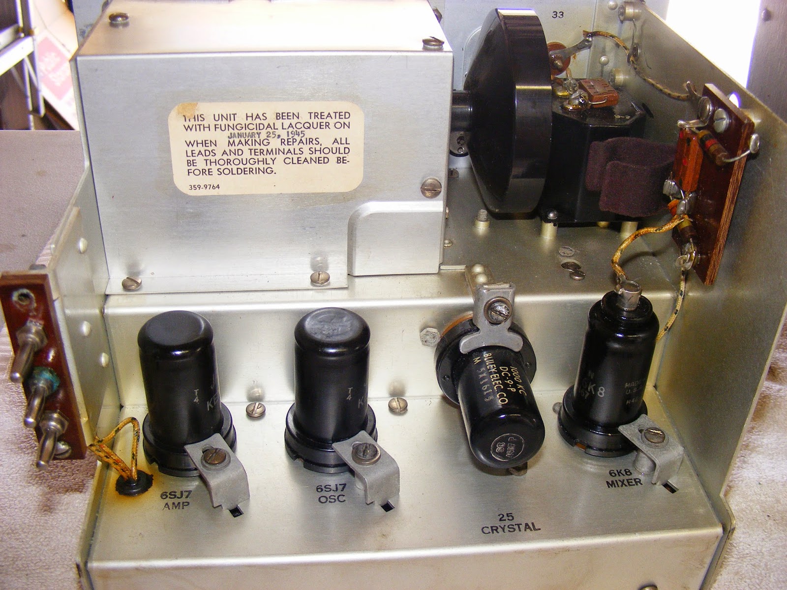
Sadly, I was on the slippery slope and it was only a matter of time before my friend in Orange had the lower range BC-221 (125 Kc though 20 Mc.) available. I think I got this for $50 or so and, while the inside was immaculate, I had to do some restoration on it. This, of course, was the BC-221-AK, manufactured by Philco for the military. The cabinet was wood and a little weather-beaten but the unit came with its original canvas flaps so the sprucing up consisted of washing and "oiling" the paint, removing the hardware and painting it either an olive drab workalike (the handle and the canvas retaining strips) or flat black (the latches). The bottom was a wreck, so I sanded it out and repainted it with the lighter shade of O.D. because it wouldn't show much. It came out beautifully as you can see from the pictures below.


Note the fungicidal warning -- issued two months before I was born!


Response to Dr Jones, "..[they're] being looked after by..top men.."

..and, soon thereafter, I was visiting the monthly Chino Hills swap meet and, of course, stumbled upon an "-F" unit (BC-221-F made by Zenith) in a little poorer condition, but good nonetheless. I restored the outer aluminum case by sanding down a wretched, pitted wrinkle finish and painting it flat black. (Hey, you restore these your way, and I'll restore these my way.)

Inasmuch as I got tired of 'documentation snaps", this went straight to the bench to revive and calibrate. But the case came out pretty good and I'll get some pics up when I revisit the revival of this unit. But these are good enough for now.


To sum up this post, the BC-221s one finds, if one looks hard enough, can be treasures and diamonds in the rough if cared for properly. However, one stumbles on some quirks and electronic restoration problems occasionally. That's what the next couple of posts will be about.

Mean time, I gotta buy Cleo a Tom Collins. Be back soon!

Wednesday, March 12, 2014

Just saved you all over $500 by reading this..

I happened to see a Chilton's Repair Guide for the Kaypro -- yes, THAT Chilon's -- and thought it might be a nice-to-have. So after casting about at the usual sites, I came up with this:

Amazon

An on-line book store

A thrift store in Washington State
Can you believe the first two? $800 plus and $600 plus? I thought maybe it's an exhaustive compendium of dark secrets, right?

So when I saw one available at the Washington state thrift shop for bout $2.00, I jumped on it. Even went for expedited shipping for a total of less than $10 delivered.

Ten days later (so much for the $8.00 speed-up mailing), it arrived and I pored over it. What a waste! I knew more than most of the stuff in there! My main interest was in the guts of the video board and principally why the display was skewed. (Please read the posts below to see what I am talking about.) The book had only FOUR pages on video boards -- two pictures, three diagrams (not including the Micrex board), and 50% of the verbiage was "there are lethal voltages running around there and you're too stupid to understand this shit anyways. Get your ass over to a professional and let him adjust the variable pots for you."

That's it!

Nuts! I am sure glad I was not rebuilding a truck transmissions; they'd probably tell me how to start the diesel and give me directions to the local GM or Ford dealer.

Oh yeah, they did have some trouble-shooting tips. You know, like
Main board does not function....Replace main board
No power........................Plug in computer
................................or replace power supply
Floppies do no spin.............Replace floppies
..etc.
..real "Rocket Surgery" stuff.

I'm outta here!

-72-

It's Captain Video and his Video Rangers

A sense of tranquility fell over the workshop late this evening. My son, the Good Lance Corporal, dragged his Suzie (Suzuki motorcyle) into the garage for some minor clean-up and we hung out as I applied the finishing touches on the Kaypro -- paying particular attention to straightening the wiggles near the bottom of the display.

This time, I tweaked the controls and noted that the was some interaction like the tech manual said. I got it petty close but could not eliminate the pronounced skew on the bottom right of the display top disappear. "Close enough for government work," comes to mind.


I also took some time to lash the new phone jack connector to the old keyboard plug and mount that. So, I'd say the old girl is about 80% I am getting some intermittent problems with getting disks to boot. Is it a symptom of the problem I encountered last Sunday? Dunno? But it would be kinda neat if I could mate this unit up with the FreHD that is being kluged into TRS-80s Mark IVs. I remember I one had an MD-DOS board inside the 2x and seeing there was little or no advantage to DOS V2.11 over CP/M, I used it as a ram disk.

Old broken phone jack and new replacement.

View of the old plug and the new phone jack with spiffy repair.

Finally wedged snugly in place.

The 2X with a slightly better editor and something better than the ECO-C compiler I was trying out tonight would be half interesting. Wonder how I can do that? Hmmmmmmmmm!

Anyway, it's back on the shelf, waiting like a good and faithful servant for the FreHD stuff to come along.


..now, in the mean time, back to the Ugly Weekender.


Monday, March 10, 2014

Kaypro 2X Back (almost) to Normal after 30 Years

After a fun-filled weekend, my old Kaypro 2X is back on the air -- sort of. The Micrex video board was re-capped and that seemed to have resolved the problem. At that point, I was a little disappointed that my quest was so easily fulfilled. It was a real no-brainer to buy some capacitors, wick out the old ones and replace them, turn it on and view the results. Moderately plain sailing.

Or so I thought.

Anyway, by way of passing on what I'd learned here's a summary of some notes I made to help others traveling along this road. Below are the initial pictures that tell the tale:

Bad K2X Display Symptoms

Captioned Micrex TW-105 94V-0 Board
Final "Semi-Fixed" Display

List of Micrex Board Electrolytic Caps

As I said, it did not turn out to be as smooth a journey as I thought it would be. After routine checkout on the bench, the reassembly turned into a nightmare. The disk drives would not boot, not spin, and and generally became non-responsive. I did a little snooping around the board and found that all the chips had the proper Vdd (+5V), the power connector yielded the proper voltages to the main board (-11V, +12V, +5V) and the drives.

I even checked a couple of signals on the board:

1 MHz Signal at pins 2, 4, and 5 of U65

2.0 MHz signal at pin 13 of u65
These weren't the only signals I scarpered. Just too busy head scratching and trouble-shooting to make a proper documentary suite of it. When things get squared away, I will revisit this and do shots for a good machine as a reference for any others wishing to revive Kaypros. (You listening, Vintage Computer moderators?)

Eventually, I determined all was working on the main board and, after testing the floppy ribbon cable and connectors, wiped down the floppy edge connector with a Q-tip and alcohol. Seems to have worked because the old girl sprang to life and booted!

I still have two problems with the video, however. (1) It's not centered vertically and (2) It's a little skewed on the bottom (see below). It may be due the the fact that I did not replace the 4.7 uF non-polarized cap; the guy at the store pulled a weensie polarized one when I was not paying attention. So, I'll get a proper cap for that and see what it does.

Wavy Gravy at work on the bottom quarter of the screen

But the vertical thing has got me buggered. There is only a "V SIZE" (V405) control and a "V LIN" control (V410) and right now, the "V SIZE" is at full throttle. The instructions in the Kapro technical manual (Jun 1985 edition) says this:


I was pretty tired Sunday afternoon but I seem to remember doing just that only it did not seem to yield the desired results. I may not have gone back and did a "dip the plate, peak the load" procedure (just like my old TS-830s) ao I'll tinker with it some more and see it that fixes it.

Another matter that needs resolution is the keyboard jack. My old one fractured and I was casting about for a replacement scheme. I had seen some folks' kluges on the Internet -- one literally looked as though the guy chewed up a wad of Double Bubble and used that to join the broken cable to the plug. (I still do not comprehend folks restoring stuff like this who will not make a proper investment in a solder station and associated education in the skill.)


I ran this by my wizard friend, John, "the knower of all things", and he pointed out a similar part to the shredded female jack in the picture above. Finally tracked it down at Digikey who got it out to me right away. I will Hoover up the order and PN info and add it if I do a post on the keyboard repair job.

Until then, it's back to the UW project and twiddling the video board pots to see if I can exorcise Wavy Gravy.


Peace!