Friday, February 22, 2013

Revisiting N6TWW's Calculations..


In a preceding post, Mike, N6TWW, discussed the calculations he made in order to develop a phasing harness for a couple of VHF antennas. I borrowed on his numbers to further ingrain this poor boy's TDR technique.
(1) Speed of light = 186,000 miles per second.

(2) 186,000 x 5,280 = 982,080,000 feet per second.

(3) 982,080,000 / 1,000,000,00 = 0.98208 feet per nanosecond.

(4) 0.98208 feet = 11.78 inches.

(5) Light travels 100% in free space but travels only as fast as the velocity factor along a cable.

(6) The velocity factors of popular cables are:

      CABLE    -  VF
      RG-8     - .66
      LMR-400  - .85
      RG-8X    - .84
      RG-11    - .75
      RG-58    - .66
      LMR-195  - .83
      RG-59    - .82
      RG-62    - .84
      RG-174   - .66
      RG-213   - .66
      RG-214   - .66
      RG-217   - .66
      RG-218   - .66
      RG-316   - .79
      RG-400   - .695
      LMR-500  - .85
      LMR-600  - .86
      1/2 HARD - .81
      7/8 HARD - .81

(7) I got 2 hunks of cable I want to determine the length of. One is a long piece of RG-8X and the other is a shorter piece of RG-58. I have another hunk of coax that I want to verify the velocity factor of.

(8) For the longer hunk of RG-8X, I assume that the velocity factor in 84% so that means that when an electron travels through it it's only going 84% as fast as its cousin in free space. Consequently, it is traveling 84% of 11.78 is 9.98952 inches. So let's say 10 inches for grins.

(9) I lashed up the scope and the function generator like these two lads did and found that the RG-8X cable's out-and-back trip was 2.4 divisions at 100 nanoseconds per division. So 100 x 2.4 = 240 and half of that (only want one-way) is 120 nanoseconds. Thus, the cable is 120 x 10 inches or 1,200 inches long. Obviously, 1,200 inches is 100 feet. (Do I really have to?) And, guess what, that's what the guy at the swap meet sold to me: 100 feet of RG-8X.

(10) The shorter hunk was 1.6 divisions at 100 nanoseconds which works out to 160 nanoseconds. The one-way time, of course, is 80 nanoseconds and, since it's RG-58, the distance traveled in a nanosecond is 11.78 x 0.66 or 7.78 inches. So electrons traveling 80 x 7.78 inches or 51.8 feet. Let me get a tape measure and check that number.

(11) Now for the third hunk of coax, I know it's 22.75 inches long and I know that it "scopes out" to 0.7 divisions and 100 nanoseconds. Half of this (one-way trip) is 0.35 x 100 or 35 nanoseconds and 35 x 11.78 or 412.3 inches or 34.36 feet.

But that's the distance in free space, and I know that the coax is 22.75 feet long. So the velocity factor would be 34.36 / 22.75 or 0.662107 or 66% -- which is what they say RG-58 should be.

Funny thing, that!
-72-

Probing the mysteries of 'scopes..

Here's the deal-e-o on scope probes:


..remember, this blog is for me and not for heavy duty PhD EE types. Sorry for my pedestrian pace.

-72-

Wednesday, February 20, 2013

Time Domain Reflectometry for the poverty stricken..

Munching my tuna fish sammich today at work and came across this:


..thought I'd store it away here for reference. Here's a practical application of this method:


Let's face it, I'm like a kid in a candy store. I am smitten with this application. Here's a variation on the same theme:


..graphic explanation for characteristic impedance and possible entre into the phenomenon of SWR? Lord, is this fun or what? I feel like one of those freaking apes at the monolith in 2001.


Ain't life grand?

-73-

Tuesday, February 19, 2013

RX2 Wrap-up..

Here's some pics just as I am buttoning it up after calibrating the unit. Lou's checkout procedures seem very cryptic at first but, after you become familiar with the operation it makes perfect sense. I plan on going back in and re-doing the unit just because I am an inveterate tinkerer. And, let's face it. I need something to do until the RX1 arrives.

"Rex, the Wonderbridge" (the RX2) along with my FT-817  ~~ affectionately, "Tex".
(I actually used to own a Sangean receiver, by the way.)
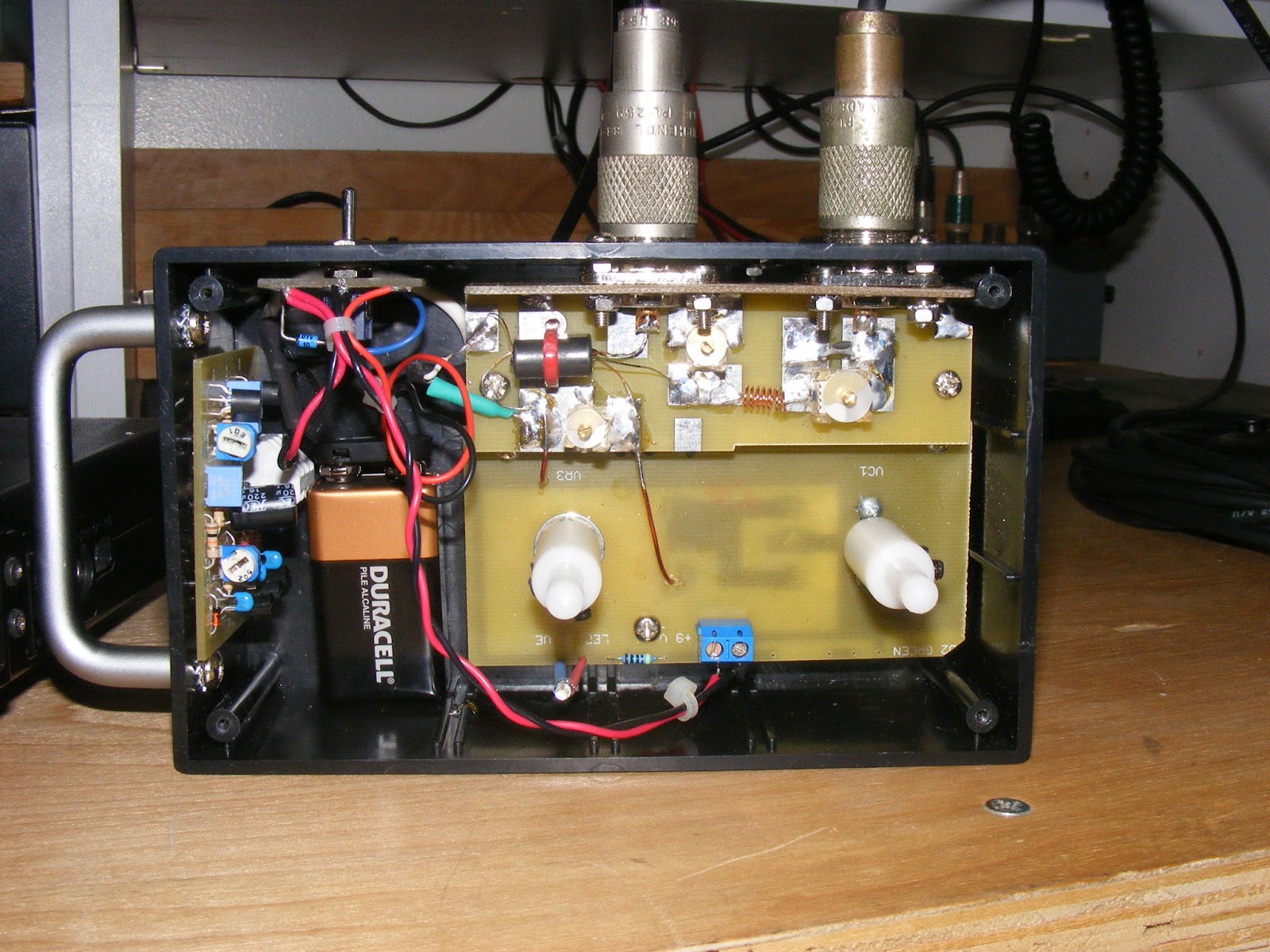
Close up internal view.
Buttoned up, next to Tex, ready for business.
Close up of the cabinet and dial.
Rex and Tex, mates for life!
The dynamic duo about to elicit some dark secrets from Mr Coax.
The pair attracts the attention of Mr Palomar, who is contemplating retirement.
Left side of the bench and the Ten Tec I am trying to breathe life into.
..and we fade out with a view of the clubhouse, our hero shutting down operations for the day and contemplating the blissful prospect of a cool one and the pleasant company of Mrs K6WHP.
-72-

Meanwhile, back at the ranch..

I guess I am like a kid in the candy store what with the wonderful things we can lay our hands on in amateur radio. Despite my seemingly wandering eye, I am having a blast with Lou's RX2. I took it to a ham radio swap meet yesterday (no pictures, sad to say) and endured the usual cretinous remarks like, "why should I use one o' them thangs? Ah gots me a MFJ 259!". Of course my churlish responses sort of morphed into, "yeah, and I'll bet you use a pocket calculator too, instead of a perfectly good slide rule!"

Jeeesh! Some people just do not get it, do they?

Anyway, with all of the components assembled, it's time to put them together. Here's a bunch of snaps with the components just prior to bolting them in and tuning the little beast up.


Nothing remarkable; just different views. You might want to check out the power switch board. Lou uses a rather simple board to anchor the power mains and the switch. Also note the LED incorporated into the RX2.  The first thought it that it will drain the battery plenty damn quick but, as a person who has left my Palomar Engineers noise bridge on more times than i care to mention, I can live with this.

Also, a follow-on comment by Lou about my trimmer inductor. He says I probably have too may turns on it to properly compensate the bridge for operation around 28 MHz. Maye so, but it tuned up nicely -- or so I think. I will be going back to revisit the initial calibration of the bridge once I get the hang of using it. I would not be surprised if Lou were correct.

-72-


Thursday, February 14, 2013

The RF board..

Now comes the fun. Take it slowly and carefully here and I recommend scrubbing RF board with alcohol and/or flux so the solder will lay down nice and smoothly with the slightest application of the iron. The traces here are huge patches of silvered copper and it's easy to build up mountains of unwanted solder and a bitch to wick the excess away. Also, the check-out/adjustment procedure requires soldering components temporarily onto these pads and then removing them. Inattention might lead to a mountainous mess.

Word to the wise. If you look closely, you can see where I was incautious with the solder on the back plane board and had to steel wool the excess away.

Also, there comes that moment of truth when you have to solder the RF board to the back plane board. Same caveat here: do not go crazy. "A little dab'll do ya."

Back plane, RF, and control board in place with transformer mounted.

Same; obverse view.

Yet more of the same from a different angle.

Here's the RF board with the components mounted

Yet more of same. See comments in this post about trim coil.

Sidelong view of RF board with mounted components

K6WHP luxuriates in his mighty efforts.

The whole magilla.

Lou provides you with the wire to wind the trimmer coil. He also provides some pre-wound springs. Here's my advice: use the springs. You will never wind a coil as neat as those springs. Also, about five or six turns should do the deed for the checkout.

Sidebar war story: I LOVE winding toroids and coils. They are probably the sexiest component in any kit. A long time ago, Doug DeMaw, W1FB, founded Oak Hills Research and they produced the OHR-100A and the OHR-500. The latter had a shit-pot full of toroids (about 20 or 30) in them and Dick Witske (who bought OHR from Doug DeMaw) apologized profusely to me when I bought the kit from him. But I told him I was on the verge of buying another one on the basis of the number of toroids.

Sure wish I kept that radio. It was all transistor; not an NE602 or LM384 in sight and quiet as the tomb. You'd tune across 40 meters in the evening with nary a hiss or crash until you came across a pure. clean CW signal. When I built mine and first turned it on, I thought the front end was dead until WB6JDH straightened me out.

-72-

The RX2 transformer..

This little beauty injects the "go juice" into the bridge so the radio can hear all the rack or the null depending on the circumstances. It's made wound on a binocular core ("Corpse" if you're Obama) and -- while daunting -- Lou's docs and pictures help you through the exercise. You just have to make sure you know where one winding stops and the other one starts.


The manual instructions has a picture with these starts and finishes marked on them. If you mind the pictures, you should do o.k. A ton of enameled wire is supplied with the kit but I had some "bare" enameled and some green enameled so I chose those to differentiate the primary and secondary windings.

I did have some red wire too, but I was getting a little "Christmassed out" and went with the bare copper look.

-72-