After having had a bit of frustration with the shaky needle, I decided to rebuild the battery pack for no other reason than a change of venue, a new adventure, and, what the hell, as my long-ago friend, W6GVR once told me, "Never try to justify a hobby."
Speaking of advice, I received some sterling guidance from yet another ham in Maine, who was in the throes of that awful winter. Herewith is a pretty good description of how the 403B does its stuff:
Howdy Bill--Anyway, back to the battery pack rebuild. You will note, if you do any research on the 403B, that it designed for long-term portable operation and the power supply is nothing more than a charging circuit for the ample batteries that comprise the entire middle compartment. (See the pictures here and in the previous post.) Mine came with four tubular batteries -- each 7 VDC when new and charged -- for a total voltage of 28 volts. These are circuited to deliver variously +/-13 volts and 7 volts to the main A2 board. (There is little else but the supply and the A2 board. See Bob's description above.) Of course, like all good things, these batteries are not readily available so some ingenuity is required to concoct a substitute.
I watched your flicks! Wow, with the behavior that I witnessed of your 403B it is virtually unusable.
I presume you've got an oscilloscope?
Mine does exactly what yours does on initial power up-- but then settles down and works properly.
On mine switching ranges the needle kicks up a little and then settles down and stabilizes on the reading within about 1/2 second.
I'm working on the house heating system here and that's got full priority-- I've got heat in the house but this is a big job that I'm not enthused about doing this repair but I've got to plod on and get it done.
I want to probe my 403B to watch what goes on at power up -- whether the amplifier(s) oscillate or gyrate at DC levels at initial power up.
I'm also curious what the meter amp does during range switching-- does it oscillate or is it a DC level shift that settles down?
The amp in the 403B may be difficult to probe with the average 'scope unless it's got a 1mV / div vertical sensitivity.
The 403B is designed as a preamp / amplifier or meter driver. It's "native" voltage range is 30 mV full scale-- "straight through". Looks like the preamp has about a 40mV dynamic range. But the meter amp has about a 15 db dynamic range-- or whatever is required to drive the 1ma meter to full scale absolute value. 1 mV into Q3 results in full scale deflection on the meter.
To get to the higher ranges HP engineers have just flanked the preamp (Q1 & Q2) with resistive attenuators. This was done to simplify the input attenuator since it has to work at high resistance. The "secondary" attenuator provides the 1-3-10 scale relation.
The preamp is a bootstrapped emitter follower. The bootstrapping feeds signal in phase from the output back to the input. This makes it look like a much higher resistance input into the preamp since less current drives into the input of the amp.
My schematic shows an 8.2M terminating resistor at the head end into the preamp.
Your meter may vary the resistance as this resistor is selected to provide a termination for the input attenuator and also provide the set meter input resistance. HP chose an emitter follower since they then drive the "intermediate" attenuator which is nothing more than a resistive divider circuit. This way they can use a low "impedance" drive into the attenuator with minimal effect on meter calibration as the user switches through the ranges. This is also done because there is little need for capacitive (or inductive) trimming on the secondary attenuator. The attenuated output from the preamp / input to the meter amp is 1MV full scale (it's probably a tad less than .001V. The emitter follower preamp can not provide any amplification-- it's only function is "impedance" transformation-- HI input to Low output to drive the 'middle' attenuator. You might call the meter driver-- Q3 - Q6 as a voltage to current converter. With .001V input to Q3 the transistor chain will generate 1MA current to drive the meter full scale. To make Q3-Q6 "constant current" a feedback path
across a low value resistor develops. This also linearizes the "steering" diodes especially at low level meter readings (when the needle is just above zero). The voltage drop across the 30 ohm resistor causes the Q3-Q6 network to develop a constant current.
OK-- you say-- so what does all this have to do with the power-up needle dance-- that I dunno yet.
And what about the reading gyrations and the jumps at range selection?
My guess is that the needle fluctuations are because Q1 or Q3 are noisy-- or both are noisy. Q1 is a potential culprit because positive feedback is used and any noise created by Q1 will be exacerbated by the positive feedback from Q2 to Q1.
Another possibility is added resistance by the switch contacts in the "intermediate" attenuator. If you look carefully you'll see that not only is there a voltage divider-- that is tapping "down value" in a resistor chain, but HP has also included series resistors looking into Q3's base. Since the meter amp (Q3-Q6) operate in the 1 mV voltage range (in order to develop 1mA to drive the meter) any added resistance drop will greatly affect the stability of the Q3-Q6 circuit. If the switch contacts are noisy that will also affect the way the meter filter capacitors C17,C18 and the one across the meter behave since those are the "averaging" devices (remember the 403B is only an average reading meter and not true RMS). I think HP recommends cleaning the attenuator switch contacts if the meter jumps around when changing meter ranges.
Kind of the same issue with Q3-- although there's no positive feedback to Q3.
The meter needle not zeroing on the low range-- (.001V) with no signal input and the meter inputs terminated with say a 10K resistor indicates to me that once again Q1 or Q3 is noisy.
You can do a quick test-- by pulling off the "Preamp out" wire (next to the loop gain adj pot). This will still leave Q3's input terminated (not floating)-- see what the meter needle does at any range. Still not zeroing? Switch from the .001V range to the .03V range. Meter zero? If there's no change it points to Q3 being noisy. Another possibility is that C17 and or C18 are leaky. If the transistors are "quiet" they're still going to create some noise level but such that you the observer can not tell that the needle has lifted from zero. But generally the meter will not deflect unless there's an "AC" or better transient signal impressed across C17 and C18. It could be possible that there's a larger than .3V drop across R35. The two diodes are biased almost "on" so that there's no "slack" when an AC signal is present and when the diodes begin to conduct. Although I don't see how this would cause the meter needle to deflect-- unless either of C17 or C18 are leaky.
OK-- I've got to get back to plumbing. I'm sending this as some food for thought.
I have to find some time to experiment with my 403B on this start up needle thing.
73s
Bob
Long story short, I cast about on eBay and discovered some NOS cordless cell phone battery packs at 3.6 volts each. Simple math reveals that eight of these will do nicely and there is not a great shoe-horning effort required to stuff them in the case. Be sure you get NiCD batteries and not NiMH. The charger/power supply will fry the NiMH batteries. Here are some pictures of the old batteries and the replacements:


It was an easy matter to join two of the original 3.6 VDC packages into one 7.2 VDC battery as the pictures show. The trick came in wiring them together to get the correct voltages the original batteries supplied but as long as you carefully disassemble the old pack, remember where the purple/black, red, blue, and striped wires hook up, you should be in good shape. I would say my only disappointment is applying the heat gun with too much vigor to set the shrink tube on the battery wires as it caused the yellow binding plastic of a couple of the packs to melt. See the picture above -- it also gives a decent pictorial on how to wire the packs in.

The diagram above is more a depiction of the battery cell hookup in terms of the old style batteries. Below is more of a schematic diagram in the event you use different cells.

By the way, they are nicely held in place by those little two-sided sticky pads from 3M.
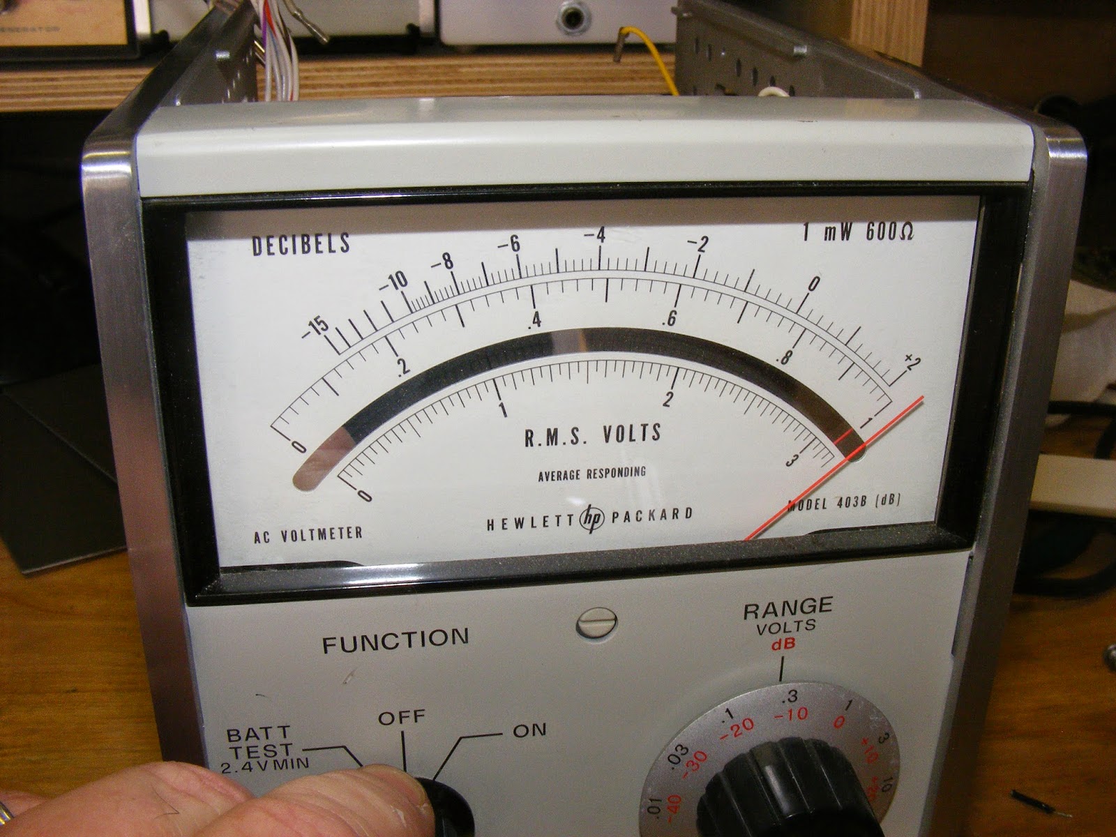
Final note on batteries and the 403B: The battery test position of the unit indicates the battery voltage divided by 10. For example, the manual cautions that the batteries need recharging when the meter reads "2.4 volts" which is, of course, 24 volts. In the picture above, my new batteries charge up in excess of 30 volts and, consequently, read off-scale. They do hold a charge as well. The unit fully charges up in the on position and has held a charge for at least a week now sitting on the shelf. (See picture at top of this post.)
Oh, and the great news about this rebuild: the meter needle is rock stable! So it seems that a dead pack was the problem after all!
Next up: the two-ground problem and some meter idiosyncrasies.
-73-
No comments:
Post a Comment