Tuesday, January 19, 2016

Two Pieces of Chinese Crap.. Interesting Developments! PIECE OF SHIT!


NEWER UPDATE
These are pieces of shit. Basically, the circuit for measuring frequency (not their goddam crystal checker circuit) doesn't work at all. I would not piss on the makers of these piles of fecal matter if they were on fire. As far as I am concerned, they can all die and go to hell with a hard-on.

That is my final word on the matter.

UPDATE
I need to do a retraction of sorts here. While I am still somewhat agitated by the lack of support by the seller of these items, I would like to go on record as saying, once revived, it appears these might actually be quite useful. Let me bring you up to date.

It seems -- after all my poking and prodding -- the second unit "woke up" and began working. Once that was in place it was a simple matter to debug the first unit -- which was truly moribund. Seeking and getting advice from Chuck Adams, K7QO, over on the QRO Tech Yahoo group, I swapped out out the PIC chip, trading the good board's chip for the bad board's chip. The fact that the good board performed correctly no matter which PIC chip was aboard revealed that BOTH chips were fine and dandy. Next, I timidly put the good board's chip into the bad board -- and yet it still slept with the fishes. Remembering back to my earlier debugging effort where checking the crystal operation on pins 15 and 16 revealed a nice clean 20 MHz trace (well, 19.997 MHz, actually) on the good board and bupkis on the other, I thought to swap out the crystal on the bad board.


Of course, these little guys are the "low-rider" HC-49/U cases and wicking out the one on the good board and soldering it into the bad board would have been dicey at best. So, reaching into my cavernous junk box, I grabbed a 16 MHz crystal (that I checked out in my PacifiCon crystal checker AND the good board's crystal checker first) and "welded" that in place.

Viola! The bad board awakened and began perking along nicely.

So I am forced to conclude it was a bad crystal all along. It cycled through the menu, saved offsets (more below) and, of course, the results of checked crystals were off by about 4 MHz. But all I had to do was get some ("Get some! Get some! Get some, baby!") new 20 MHz crystals and I'd be set.

I pulled the trigger on a local auction (to hell waiting a fortnight for some guy in a warehouse in China get around to sending me them), and was the proud owner of what I thought was six or seven 20 MHz jobbies. Sadly or happily, the quantity count turned out to be FIFTY!

Oh well.

Remember the 19.997 MHz comment above? Well the good board was off by 3 KHz so it seems as though a the 19.997 MHz may be causing the error. The price was right on the batch that I got, so I can wade through all fifty, find one or two of them dead on, and swap out the old crystals for the new accurate ones.

Another plus of the design is deriving the offset if this is going to be used as a frequency display for a radio. You merely go into menu mode, measure the IF of the radio in question and then press "ADD" or "SUB" to obtain the appropriate offset and call it a day. The VFO frequency will then be ADDed or SUBed to the stored offset and Bob's your uncle. I am guessing that you can also set the IF by using a signal generator. How the hell will the counter know?

Add to the fact that the plastic case looks kind of nice -- much better than saving a few bucks and putting the display in some kludged-together pile of soldered PCB.

So, looks like the rain clouds are parting and the sun is coming out after all.

ORIGINAL POST
O.K., so there's only one in the picture. But I bought two of these units off eBay from a Chinese dealer in the mysterious Orient and it turns out that the only goddam thing that was mysterious about BOTH units was that they did not work when I assembled them.

What a waste of time and money. Oh, they do offer a money back guarantee but one has to go through the effort (and cost) of mailing the crap back to those pirates.

And, yes, I assembled them both carefully. And, yes, because the first one did not work, I MEASURED and TESTED each part I put onto the board of the second one. And, no, neither one worked.

But to be fair, the second one worked for a few minutes and then crapped out. And, when it did work, it blinked and gagged out some mysterious prompts via the display. Pushing the button only brought on more weird behavior and mysterious prompts before it finally faded into oblivion. Of course, I had given the dealer a positive rating when the packages arrived. And, of course. I sent the dealer a message telling him that his piles of Chinese crap sucked. (I was more polite than that. Next message will not be.)

But to my original cause for aggravation over these units: the single piece of toilet paper that the Chinglish instructions were written on. You know, the ones with the microscopic printing and faded, unintelligible diagrams. (I don't expect a damn Heathkit manual, but they could have invested a little more effort in the instructions, fer crissakes!) And as for operating instructions once these are up and running? Non-existent. Not a whisper of a hint of a breath of a word about how to measure frequencies or crystals or set the offsets.

Nothing!

..which is what these are worth.

Saturday, January 2, 2016

One Watter: Watt's up?

Just so you don't think my workbench is orderly and immaculate all the time..

The workbench in mid-crisis.
I was closing in on the finish and had added the final amp and output bandpass filter (actually completing the build) and was testing/aligning the radio when I hit a bump in the road. Try as I would setting the output power to one watt, I could not goose the little beast over 0.7W out. I peaked the bandpass filter over and over again. I check out the parts, solder joints, etc. but could not budge the output power past that level..

..at least that's what my OHR WM-2 watt meter was telling me.

My OHR telling me it's only 0.5W out.

But my trusty, rusty 7704 sang a different tune:


Consulting with my arch-friend, WB6JDH, and doing a little research, I came across a tour de force slide presentation entitled Math for the General Class Radio Operator that N9XH did for the ARRL and those sources cleared a lot up for me. Here are four salient slides from that presentation, right in the wheelhouse with respect to addressing this situation. They are self-explanatory:


So, extrapolating from the above,

(1) Determine total peak-to-peak volts:

4.8 divisions x 5 volts per division = 24 volts peak-to-peak

(2) Convert from peak-to-peak to RMS:

24 volts peak-to-peak / 2 = 12 volts peak x 0.7070 = 8.484 volts RMS

(3) Now solve I = E/R for I (current in amps):

I = 8.484/ 50 ohms = 0.16968 amps

(4) Now solve for P = I x E (power in watts):

P = 8.484 x 0.16968 = 1.440 watts

But Dick simplified this by using .3535 (half of 0.7070) and skipping the determination of the current and squaring the voltage. I will leave you to derive that, but it works out the same:

(1) 24 volts peak-to-peak x 0.3535 = 8.484 volts RMS
(2) 8.484 RMS volts squared = 71.918
(3) 71.978 / 50 ohms = 1.440 watts
Although it is good to know the derivation, I am going with Dick's method as it is shorter and handheld calculator friendly. Anyway, however you run the numbers, it works out to 4 divisions being damned close to 1 watt. (About 0.996 watts, actually.)

Now here's the rub. I went back and re-ran the calibration on my OHR WM-2 and it *still* came out around 0.7 watts when the 1-Watter output was set to 4 divisions (20 volts peak-to-peak) on the scope and I cannot explain away the difference. Trying a couple of other watt meters I had in on the bench, I found a some were "inaccurate", but a Diamond SX-200 was "dead on".

I guess it's why I call this "the man with two watches" syndrome. You know - a man with one watch knows what time it is; a man with two watches is never quite sure.

Failing a plausible explanation for the differences and trusting in my scope (a calibrated Tektronix 7704) as being the most accurate source -- AND since my other measurements of various circuit points on my 1-Watter substantially agree with those presented in K7QO's Phase 8 and Phase 9 videos, I deemed that the standard. And, actually, went back to calibrate the OHR WM-2 using the 1-Watter as a reference.

Now, here's an interesting factoid in this which lends to the mystery. About four weeks ago -- sometime around the first part of December 2015 -- wanting to give QRPp (QRP operation at one watt or less) a try, I got out my old NorCal 40A and set it to one watt using the OHR WM-2! Going back and measuring the NorCal 40A with the same WM-2 used to set it to one watt out, I got a similar 0.7 watt output reading. Netiher the WM-2 nor the NorCal 40A was touched in the interim.

Strange, huh?

Anyway, my final pronouncement on the 15 Meter 1-Watter is that it is a fun kit, very reasonably priced, and with Chuck and Diz's documentation, and excellent source of knowledge for the builder who wants to be much more than an appliance operator or "Baofeng Tech".

"Who knows what evil lurks in the heart of.."

"I do, old son.."

-72-

Friday, January 1, 2016

One Watter: Phase Four through Phase Eight..

I didn't necessarily blast through the middle and ending phases but I did not document them as thoroughly as I should have. (In fact, I did not document the first phases that completely either. Pretty much a bunch of pictures with comments. But then again, I did so for the following reasons:

(1) I was lazy.
(2) I was absorbed in the building process.
(3) I was learning as much as I could.
(4) Chuck Adams did a better job than I could ever do.

So here's up to Phase Eight -- the driver stage. Everything up through this stage checked out fine and I was set to sail through the last stage (the final and the output bandpass filter) when I hit a bump which I will describe in a final post. However, the bottom line was that the rig ultimately passed with flying colors and is waiting for a home.

So here's some pictures and comments for the last phases.

The T5 transformer on the 15m 1-Watter is wound on a BN-43-2402 binocular core and is actually pretty simple once one realizes that a complete turn is one pass through BOTH holes. (It is, therefore, possible to do a half turn.) If you follow the instructions re wire size and wind the 8-turn secondary first, it's a piece of cake.

T5 wound and ready to go. This one looks like the alien in Independence Day, don't it?

T5 in situ..

..ibidem.

Left is T4 (VXO circuit) and L1 or L2 (output bandpass filter). (They are identical).

Here is T4 along with L5 in the VXO circuit. Note L5 (left) was wound with 40 turns.

The primary windings of T2 and T3. They require a 1-turn loop for this secondaries.

The whole board just before adding the driver and final stages.

The completed driver stage with T1 in place. Note that this is an FT-37-61, the dull grey toroid.

Whole board up through the driver stage.


The tricky part is adjusting the pre-driver bandpass filter -- between C23 and C24 but that is only marginally nigglesome to adjust. For the transformers in this stage. Diz recommends an alternative of stripping the entire length of the one-turn secondary for each of these transformers but I opted to use semi-long pieces of bare clipped component leads I had lying around. They were more riggid and saves me the work of tinning, etc.

Also, be sure you get T1 and L4 wound on the correct core. T1 is wound on the FT37-61 core which is dull grey. L4 is wound on an FT37-43 which is blacker and more shiny.

..on to my final adventure!

-72-

Sunday, December 27, 2015

One Watter: Phases Two and Three

I continue my build of the 15 meter One Watter by Diz and Chuck Adams:

Phases Two and Three
I have taken Chuck's Phase Two and Phase Three and combined them into this post. Basically, he has you build then keyer circuit and install and test the chip. Additionally, the transmit keying circuit and receiver muting circuits are tested.

Project schematic completion.

Audio and keyer circuits.

Whole board including the keyer circuit and muting circuit.
While these two phases sound impressive and you'd figure that the testing would be extensive but it's really quite simple. Here, Chuck powers up the board WITHOUT a new chip inserted in a newly built section and tests for the proper DC voltage at the appropriate IC socket pin. This is also important because there are three types of voltage regulators in this project: a 78L05 for the audio circuit, two 78L08s for the receiver mixer and transmitter, and a 78L10 for the VXO and it allows you to double check that the regulators are installed in the proper places.

The Phase Three checkout involves setting the keyer into straight key mode and then keying the unit and measuring various places around the board to see it the keying circuit sends +12 volts when keyed.

Up next is Phase Four which tests the newly constructed demodulator to see if you can get an 8,064 kHz signal through U6 into the audio chain.

-72- 


Saturday, December 26, 2015

One Watt, a ton of fun..Phase One

As I posted re Breadboard Radio's Sawdust Regen kit, I have been on a building jag these past three to four weeks. I guess the main reason is that my boss at work is a hopelessly disorganized individual who invites chaos at every turn and has no compunction about spreading his quiet desperation around to others.

(As a sidebar, he is almost universally disliked by his charges who almost openly ridicule him and make jokes about this foibles. But this gives me little comfort and the confusion he causes leads me to seek an orderly, constructive existence elsewhere. It would seem, psychologically speaking, that this building is an effort for me to bring order back into my life. Hopefully, I shall be retired by this time next year and never, ever have to deal with incompetent management and disorganized assholes for the rest of my life. But I digress. Sorry to burden you further.)

In any event, I discovered W8DIZ's One-Watter single-board kits. Diz operates Kits and Parts Dot Com and who, in response to Chuck Adams' request for a rig that could be used by people as an inter-room, over-the-air code practice device helped Chuck develop a single-board transceiver that was so superior in design and concept that many are using it to further their QRPp endeavors. Originally, Chuck Adams, K7QO, prepared a 10-part video of excellent quality but it has disappeared into the vapor so we will have to do without.

In any event, I tumbled for two of these kits -- 20 meters and 15 meters -- and am enjoying a Christmas/New Year's holiday off from work (and my boss) building these.

Truly relaxing.

Chuck's methodology is to build and test segments of these radios as his video series will point out. So, I thought what more fitting way to embark on this adventure than to follow in Chuck's footsteps -- and his videos -- and build the 15 meter rig in phases. Also, by way of adding to the pantheon of knowledge regarding these kits, I would offer notes about my travails and triumphs. Probably might be a good idea to intersperse these with some other facts about the One-Watter phenomenon and other sanguine comments.

So here goes:

Phase One
Started out this project by organizing my work area to implement Chuck's methodology. He likes to mark a full-page schematic as he installs parts and I opted to do the same. In addition, Diz's kits uses the infamous 1/8th watt resistors and my eyes are becoming too feeble to discern colors -- even to the point where my magnifiers will not help. (See the problems I had with the resistors in the Sawdust Regen kit in the previous post.) Consequently, I found the cheapie Chinese component tester I got some months ago to be an indispensable tool for identifying resistors. Guessing that device will never leave my side for future projects.

As Chuck explained in the video above, Phase One consists only of ensuring that 12 volts negotiates the reverse-polarity 1N4007 diode and arrives at the proper pin of the LM396 socket. Also, the LM386 audio amplifier circuit is checked out to see if it working. I was skeptical of this because of my experience with the QST version of the WBR regen receiver and Chuck's comment about the speaker volume being faint. However, I was pleasantly surprised that the circuit provided a lot of volume and am led to believe that the unit will be perfectly suitable for unamplified speakers when put into operation. Pictures below:

Workplace. Not as gloomy as it seems just the flash didn't fire. Note component tester.

Phase One completed with audio circuit.

Audio section.

Radial 100 nF cap substituted for 100 nF SMT cap at C36.

Close up of same. Solder flux has been cleaned away. Cap will be lain flat when board completed.

Phase One schematic progress. Note R12 installed to facilitate C36 replacement.

I would add these notes to my Phase One effort: pay special attention to where Chuck says to go ahead and install ALL of the the SMT caps first if you want to. He mentions it and I pestered Diz who confirmed that installation of same would not adversely affect the "Build and Test" paradigm. Also, note Diz's correction in the addendum (and my pictures above) wherein he recommends NOT installing the C36 SMT cap but rather putting in the axial cap from one of the C36 pads to ground. I asked Diz about this and he says that there was an error in the PCBs dated 09/03/2015 ~~ see the "20150903" below the DC connector holes in the upper right. To quote Diz:
Hi Bill,

Take a look at C36 on the schematic....it connects from ground to the gates of Q8/Q9. Now look at the PCB...it connects C36 from the gates of Q8/Q9 to pin 4 of U4.

The PCB is in error...also known as a royal screw up. Easiest way around the error is to solder an axial 100 cap on the bottom of the PCB. The PCBs is error are silk screened with 20150903.

See http://kitsandparts.com/1watter15u.php

Any PCBs after 20150903 are corrected.

See http://kitsandparts.com/1watter30u2.php

73, Diz, W8DIZ

Parting comment on the LM386 audio amp circuit: I had a spare LM386 N3 rattling around on the bench from my WBR effort and plugged that in when doing Chuck's audio test. (I was too lazy to go rooting around in the kit parts bag.) The audio -- with headphones -- was more than adequate. When I swapped in Diz's kit-provided LM386 N4, it was almost ear-splitting. Again, this leads me to believe that this little rig will perform just fine with in a room with a speaker -- provided the room is not Carnegie Hall.

Anyway, all seemed to check out just fine. On to Phases Two and Three.

-72-

Sawdust Festival

Sorry; this is going to be long because it draws on remembrances of my misspent youth and, well, this is my blog and you can pound sand or go elsewhere if you lack the requisite attention span.

A long time ago when I was a kid at college attending UCLA, my main squeeze and I used to visit Laguna Beach in the Summertime and chiefly during their Festival of the Arts. Now Laguna Beach was then -- as now -- a pretentious, overstuffed haven for artists attempting to wring out yet one more mural of the Orange County coastline that the city sits on and also wring out yet one more dollar from the tourists who ventured down there for their shops, restaurants, and other venues that purveyed the treacly, maudlin, kitsch, and largely unfresh goods and paintings that delight old blue hairs and who drag their paunch, bald-headed, Bermuda-short clad hubbies for an afternoon or weekend of "terminal quaint". The same held true for their annual Summer "Festival of the Arts" where those tiresome moonlit seascapes with the translucent wacves crashing on the sand beaches or YET ANOTHER view of the Laguna Hotel form the Gazebo. (You had to have been there.) In any event, this soiree transpired back up Laguna Canyon aways at a location that charged a stiff tarriff to enter. As it was with the times those days, the 60s were in full tilt boogie, having just passed the Summer of Love and hippies and dead heads were springing up all over.

Laguna was not to be denied.

Seems that a collection of artists set up camp in a vacant lot -- with the permission of the owner, a la Max Yasgur of Woodstock fame -- and began a FREE showing and selling of their fresh, new, and interesting crafts. It drew throngs of folks who both rebelled at the stuffy art show across the street and reveled in the novelties on offer. The beauty of these pieces were in the observer remarking, "How marvelous; why didn't I think of that?" The point was, that the stuff was interesting, enchanting, and bore the true craftsmanship of someone who had an elegantly simple but interesting idea and the skill to bring it to life.

Sadly, The Sawdust Festival is now become a over-imitated parody of itself, charges admission, and is fraught with crass commercial goods. But the memory of the fun lingers.

So it is with this fresh, new offering (among several), from a gentleman in Columbia, South Carolina -- Bill, W4FSV -- laboring under the mantle of the truly unique and interesting title of Breadboard Radios whose products are among the neatest I have seen for weeknight or weekend projects. Among his products is one Sawdust Regen Receiver and it has to be one of the more interesting kits I have seen/built in a long time. Here is his original picture from his website:


..with usual caveats regarding his copyright privileges and how I will pull it is Bill objects to its use, etc. Bill's products evince a wood/woodworking theme -- the Splinter II QRP Receiver/Transmitter, The Toothpick Audio Filter, The Matchstick Tuner, and my personal favorite (aside from the Sawdust Regen), the Woodstain "Cantenna-like" Dummy Load:


Anyway, I have been on a building jag for the last two months (and it is likely to continue) with most of it centered around breathing life into various incarnations of the venerable Regenerative Receiver, a design that predates the superheterodyne but is simple and very sensitive. However, thrashing about in a number of QST articles -- the N6BYT WBR regen and the Kitchin Scout Regen -- and producing largely unsatisfactory results, I was frustrated to actually breathe line into a regen, kit or otherwise. The two circuits mentioned were built on PCBs by Far Radio Sales, whose quality was good and could have worked were it not for the monumental editing errors in the QST articles and the lack of intuitive electronic ability of yours truly.

To be fair to N6BYT and the WBR, the QST article was so fraught with contradictions -- even in the follow-up stays -- that it was extremely hard to bring off. I will be attempting to mimic the excellent work done by Dave Richards, AA7EE, whose WBR is a true work of art. But he did his with QRPMe squares and Manhattan construction and added an interim 2N3904 amplifier stage before the LM386 audio amp. The QST article only had a pathetic implementation of the LM386 that only produced whispers barely heard on ear phones.

Very unsatisfying.


So that was when I stumbled across the The Sawdust Regen as shown in this video on you tube:


..and the hook was wet, so I sent Bill $25 for the unit (includes shipping, I believe) and, less than a week later (even during the heavy Christmas season mailing log jam), I received my kit. I took an evening and put this together -- working carefully -- and was absolutely delighted with the result once I worked a couple of self-imposed kinks out; see comments below after the pictures.

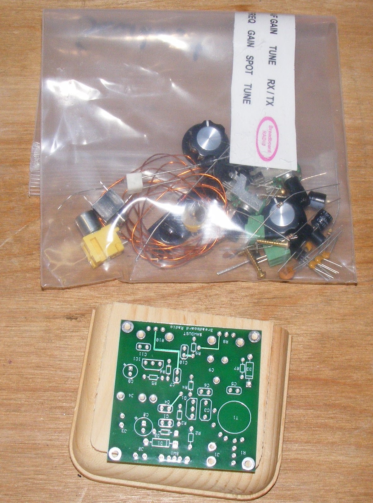
Kit as received with PCB, base, and bag o' parts. (Knobs included!)

Radio base in keeping with Bill's woodworking theme

Not an alien but the main coil. It is imperative that winding instructions are followed! 

The main coil -- in situ

The alien reaching out for a victim?

Finished underside of board.

Finished top side of board. Note screw connectors. 

Finished kit - top left view.

Finished kit - top right view.

Finished kit - top straight on view.

Finished kit - well, you get the idea.
Anyway, there are several more points to make before closing this out. Firstly, read the freaking manual! O.K.? So, read it again and again and again..until you are familiar with it. I breezed through the instructions because I was the smartest guy in the room and I made a couple of errors -- fortunately not serious.

Be absolutely certain that you follow the coil-winding instructions to the letter! I did not at first but, before putting the coil on the board, I double checked my work (and the instructions) and discovered that it is important to wind the turns on the coil (there are three separate windings) in a certain direction or the radio will not work.

Also, those 1/8th watt resistors are mighty small and it is hard to read the color stripes -- SO BE SURE the resistor you are mounting is correct. I confused the 47K resistor for the 470K  (or something) and I heard nothing when I put the coal to the radio. Extracting and swapping the resistors destroyed them so I dove into my junk box for replacements. (I only had 1/4th watt resistors but they could be mounted vertically on the board just fine.)

Oh, and these cosmetic issues: your friend, the genius, did not read the instructions and tried to peel the labels off their backing with no success. Then I found out that they were decals (just like the models you built as a kid) but it was too late. So, I cut the the remaining decal labels (I still did not have a clue) and glued them to the base after I finished it with some Danish oil I had on hand. I let it dry in the sum for about two hours and coated it with some Krylon clear coat and it turned out just fine.

When all was ironed out, I tested the radio and found that, once aligned and set, it could cover approximately 6,900 kHz through 7,120 kHz -- more than adequate for coverage of the 40 meter CW band. I will probably re-tune it to listen to the upper part of the band -- SSB or AM -- or even higher to hear the AM broadcast stations around 7,300-7,420 kHz.

But it is a great radio and fun to build. It cannot work miracles -- especially in my crappy location -- but when 40 meters is in (most nights), it's very sensitive using a short wire antenna and has a crisp, clear sound with plenty of audio to drive a set of headphones. And, believe me, this little project is one hell of a lot better than running down the errors and foibles of those hoary old QST articles.

Give it a try! Guarantee you will have a building and using it.

-72-

Sunday, December 20, 2015

Annual QST DIY..

Tis the season to be grinchy.


Just received my latest QST -- the January annual DIY issue -- and, rubbing my hands with glee, I sat down yesterday for a browse. It did not disappoint; loaded with a lot articles scraped form the bottom of the barrel that makes one wonder who really takes this shit seriously. Some samples and my crusty, salty comments:

A 3D Printed Key for Straight Key Night
One of those pillowy, brickish white things off a 3D printer. Looks like the key the Pillsbury Dough Boy would use. So, lessee, you drop several centabucks on a 3D printer to make one of these things..or, plunk down about $20-80 for a vintage J-38 and do SKN in style. Hard choice.


Using Unmodified Command Set ARC-5 Radios on the Ham Bands
The article concedes that the unmodified versions of these "command a significantly higher price than the modified ones". Yea, have you been out to ebay and seen the criminals sticking up the public for MilSurp gear? And the chances of finding an unmodified command set at a swap are slim and none. And "slim" is outta town. Plus with the unmodified ones, you have the dubuious pleasure of all those rotten, leaky old beeswax caps to deal with. You know the ones that double as 250 KOhm resistors?

Pass.

The Double-Nickel QRP Key
..another of those tin-snip-and-bolt-together beauties that are of dubious value because they have no weighted base nor tensioning/space adjustments. Again with the eBay vendors who sell decent products at a reasonable cost that are much more able to cope with my epileptic fist.

Desk Microphone Power-On and PTT Indicators
Mod your high-priced Icom SM-2D with a PCB and NPN-toggle device that turns on two small LEDs in the base of the mic when (1) the power is on and (2) you are yammering away with some other dolt on 14,275 KHz about the neat mod you made to your mic.

Like John Wilkes Booth once said, "Useless, useless."

Done in One: Battery Backup for your Wall Wart
Subtitle says it all: "Ride through the line interruptions with this handy device."

Wonder if these guys have ever heard of, ummm, oh, I don't know, running your station off of a battery in the first place?

You Too, Can Work 630 MetersAn article form one of the FCC-authorized hams allowed to experiment on 472-479 Khz wherein he advises that he scored a backup JRC NSC-17M transmitter from an auction of stuff from a commercial ship. Of course, like unmodified command sets, we have these things floating around all over the place.

..so, to avoid the rise in the subscription rate (and save about $50), I renewed QST for three years.

..please note, all pics and images (c) ARRL.

Bah, humbug!
-72-