After having repaired my 7D15 freq counter plug-in (a questionable cap, bad solder joint, and some pilot error), I am turning my attention to a 7D14 that is flaky. Below are the facts.
(1) Problem is that the 7D14 stops displaying the
frequency correctly -- i.e., displays all zeroes - when the signal is sourced from a
vertical amp. I have tested with a signal input from the unit's front
panel BNC and it does seem to not fail.
(2) The problem seems heat related.
(3) The set up is as follows:
(a) Scope is 7704A.
(b) 7A26 in left vertical slot.
(c) 7B92A in horizontal slot A.
(d) 7D14 in in horizontal slot B.
(e) Vertical mode LEFT.
(f) Horizontal mode A.
(4) Other settings per 7D14 manual troubleshooting/calibration set up.
(5) Signal input to Channel 1 on 7A26 and adjusted to AC, set to display and trigger on channel 1.,
(6) 7D14 set 10 ms, Trigger Preset, 525 MHz, AC, TRIG SOURCE, and frequency is displayed correctly on CRT.
(7) After about 1-2 hours, the frequency display becomes erratic and then displays all zeroes.
(8)
Removing the side panels on the scope and the plug-in and blowing it
with cold air causes the frequency to be displayed properly.
(9)
Leaving the plug-in exposed (no side panels) causes it to run
indeterminately longer without failing. (That is, I have let it run
several hours without failure.)
(10) Similarly, I have set it up
to read a signal input from the CH A INPUT BNC in the 7D14 front panel
and -- even when covered with the side panels -- it seems to run a long
time and not fail. (Similarly, I have let it run several hours without
failure.)
In looking at the manual and reading the schematic and
notes, I am guessing that the vertical input from the 7A26 arrives on
pins 20A (+TRIG IN TO T870) and 20B (-TRIG IN TO T870) and, accordingly,
I have begun to snoop through schematic <1> CHANNEL A SIGNAL
CONDITIONING but sense that I may be a little off. I thought I'd document my fix here if I am successful.
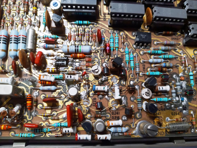
Below are some pictures of the two PCBs in the unit in no special order. If you click on them they will enlarge for a more detailed view. Subsequent posts will track my progress and I'll also mark up the photos below -- if needed -- to highlight areas of importance involved in my problem resolution.
High Frequency Board
Logic Board


No comments:
Post a Comment