I continue my build of the 15 meter One Watter by Diz and Chuck Adams:
Phases Two and Three
I have taken Chuck's Phase Two and Phase Three and combined them into this post. Basically, he has you build then keyer circuit and install and test the chip. Additionally, the transmit keying circuit and receiver muting circuits are tested.
Project schematic completion.
Audio and keyer circuits.
Whole board including the keyer circuit and muting circuit.
While these two phases sound impressive and you'd figure that the testing would be extensive but it's really quite simple. Here, Chuck powers up the board WITHOUT a new chip inserted in a newly built section and tests for the proper DC voltage at the appropriate IC socket pin. This is also important because there are three types of voltage regulators in this project: a 78L05 for the audio circuit, two 78L08s for the receiver mixer and transmitter, and a 78L10 for the VXO and it allows you to double check that the regulators are installed in the proper places.
The Phase Three checkout involves setting the keyer into straight key mode and then keying the unit and measuring various places around the board to see it the keying circuit sends +12 volts when keyed.
Up next is Phase Four which tests the newly constructed demodulator to see if you can get an 8,064 kHz signal through U6 into the audio chain.
As I posted re Breadboard Radio's Sawdust Regen kit, I have been on a building jag these past three to four weeks. I guess the main reason is that my boss at work is a hopelessly disorganized individual who invites chaos at every turn and has no compunction about spreading his quiet desperation around to others.
(As a sidebar, he is almost universally disliked by his charges who almost openly ridicule him and make jokes about this foibles. But this gives me little comfort and the confusion he causes leads me to seek an orderly, constructive existence elsewhere. It would seem, psychologically speaking, that this building is an effort for me to bring order back into my life. Hopefully, I shall be retired by this time next year and never, ever have to deal with incompetent management and disorganized assholes for the rest of my life. But I digress. Sorry to burden you further.)
In any event, I discovered W8DIZ's One-Watter single-board kits. Diz operates Kits and Parts Dot Com and who, in response to Chuck Adams' request for a rig that could be used by people as an inter-room, over-the-air code practice device helped Chuck develop a single-board transceiver that was so superior in design and concept that many are using it to further their QRPp endeavors. Originally, Chuck Adams, K7QO, prepared a 10-part video of excellent quality but it has disappeared into the vapor so we will have to do without.
In any event, I tumbled for two of these kits -- 20 meters and 15 meters -- and am enjoying a Christmas/New Year's holiday off from work (and my boss) building these.
Truly relaxing.
Chuck's methodology is to build and test segments of these radios as his video series will point out. So, I thought what more fitting way to embark on this adventure than to follow in Chuck's footsteps -- and his videos -- and build the 15 meter rig in phases. Also, by way of adding to the pantheon of knowledge regarding these kits, I would offer notes about my travails and triumphs. Probably might be a good idea to intersperse these with some other facts about the One-Watter phenomenon and other sanguine comments.
So here goes:
Phase One
Started out this project by organizing my work area to implement Chuck's methodology. He likes to mark a full-page schematic as he installs parts and I opted to do the same. In addition, Diz's kits uses the infamous 1/8th watt resistors and my eyes are becoming too feeble to discern colors -- even to the point where my magnifiers will not help. (See the problems I had with the resistors in the Sawdust Regen kit in the previous post.) Consequently, I found the cheapie Chinese component tester I got some months ago to be an indispensable tool for identifying resistors. Guessing that device will never leave my side for future projects.
As Chuck explained in the video above, Phase One consists only of ensuring that 12 volts negotiates the reverse-polarity 1N4007 diode and arrives at the proper pin of the LM396 socket. Also, the LM386 audio amplifier circuit is checked out to see if it working. I was skeptical of this because of my experience with the QST version of the WBR regen receiver and Chuck's comment about the speaker volume being faint. However, I was pleasantly surprised that the circuit provided a lot of volume and am led to believe that the unit will be perfectly suitable for unamplified speakers when put into operation. Pictures below:
Workplace. Not as gloomy as it seems just the flash didn't fire. Note component tester.
Phase One completed with audio circuit.
Audio section.
Radial 100 nF cap substituted for 100 nF SMT cap at C36.
Close up of same. Solder flux has been cleaned away. Cap will be lain flat when board completed.
Phase One schematic progress. Note R12 installed to facilitate C36 replacement.
I would add these notes to my Phase One effort: pay special attention to where Chuck says to go ahead and install ALL of the the SMT caps first if you want to. He mentions it and I pestered Diz who confirmed that installation of same would not adversely affect the "Build and Test" paradigm. Also, note Diz's correction in the addendum (and my pictures above) wherein he recommends NOT installing the C36 SMT cap but rather putting in the axial cap from one of the C36 pads to ground. I asked Diz about this and he says that there was an error in the PCBs dated 09/03/2015 ~~ see the "20150903" below the DC connector holes in the upper right. To quote Diz:
Hi Bill,
Take a look at C36 on the schematic....it connects from ground to the gates of Q8/Q9. Now look at the PCB...it connects C36 from the gates of Q8/Q9 to pin 4 of U4.
The PCB is in error...also known as a royal screw up. Easiest way around the error is to solder an axial 100 cap on the bottom of the PCB. The PCBs is error are silk screened with 20150903.
See http://kitsandparts.com/1watter15u.php
Any PCBs after 20150903 are corrected.
See http://kitsandparts.com/1watter30u2.php
73, Diz, W8DIZ
Parting comment on the LM386 audio amp circuit: I had a spare LM386 N3 rattling around on the bench from my WBR effort and plugged that in when doing Chuck's audio test. (I was too lazy to go rooting around in the kit parts bag.) The audio -- with headphones -- was more than adequate. When I swapped in Diz's kit-provided LM386 N4, it was almost ear-splitting. Again, this leads me to believe that this little rig will perform just fine with in a room with a speaker -- provided the room is not Carnegie Hall.
Anyway, all seemed to check out just fine. On to Phases Two and Three.
Sorry; this is going to be long because it draws on remembrances of my misspent youth and, well, this is my blog and you can pound sand or go elsewhere if you lack the requisite attention span.
A long time ago when I was a kid at college attending UCLA, my main squeeze and I used to visit Laguna Beach in the Summertime and chiefly during their Festival of the Arts. Now Laguna Beach was then -- as now -- a pretentious, overstuffed haven for artists attempting to wring out yet one more mural of the Orange County coastline that the city sits on and also wring out yet one more dollar from the tourists who ventured down there for their shops, restaurants, and other venues that purveyed the treacly, maudlin, kitsch, and largely unfresh goods and paintings that delight old blue hairs and who drag their paunch, bald-headed, Bermuda-short clad hubbies for an afternoon or weekend of "terminal quaint". The same held true for their annual Summer "Festival of the Arts" where those tiresome moonlit seascapes with the translucent wacves crashing on the sand beaches or YET ANOTHER view of the Laguna Hotel form the Gazebo. (You had to have been there.) In any event, this soiree transpired back up Laguna Canyon aways at a location that charged a stiff tarriff to enter. As it was with the times those days, the 60s were in full tilt boogie, having just passed the Summer of Love and hippies and dead heads were springing up all over.
Laguna was not to be denied.
Seems that a collection of artists set up camp in a vacant lot -- with the permission of the owner, a la Max Yasgur of Woodstock fame -- and began a FREE showing and selling of their fresh, new, and interesting crafts. It drew throngs of folks who both rebelled at the stuffy art show across the street and reveled in the novelties on offer. The beauty of these pieces were in the observer remarking, "How marvelous; why didn't I think of that?" The point was, that the stuff was interesting, enchanting, and bore the true craftsmanship of someone who had an elegantly simple but interesting idea and the skill to bring it to life.
Sadly, The Sawdust Festival is now become a over-imitated parody of itself, charges admission, and is fraught with crass commercial goods. But the memory of the fun lingers.
So it is with this fresh, new offering (among several), from a gentleman in Columbia, South Carolina -- Bill, W4FSV -- laboring under the mantle of the truly unique and interesting title of Breadboard Radios whose products are among the neatest I have seen for weeknight or weekend projects. Among his products is one Sawdust Regen Receiver and it has to be one of the more interesting kits I have seen/built in a long time. Here is his original picture from his website:
..with usual caveats regarding his copyright privileges and how I will pull it is Bill objects to its use, etc. Bill's products evince a wood/woodworking theme -- the Splinter II QRP Receiver/Transmitter, The Toothpick Audio Filter, The Matchstick Tuner, and my personal favorite (aside from the Sawdust Regen), the Woodstain "Cantenna-like" Dummy Load:
Anyway, I have been on a building jag for the last two months (and it is likely to continue) with most of it centered around breathing life into various incarnations of the venerable Regenerative Receiver, a design that predates the superheterodyne but is simple and very sensitive. However, thrashing about in a number of QST articles -- the N6BYT WBR regen and the Kitchin Scout Regen -- and producing largely unsatisfactory results, I was frustrated to actually breathe line into a regen, kit or otherwise. The two circuits mentioned were built on PCBs by Far Radio Sales, whose quality was good and could have worked were it not for the monumental editing errors in the QST articles and the lack of intuitive electronic ability of yours truly.
To be fair to N6BYT and the WBR, the QST article was so fraught with contradictions -- even in the follow-up stays -- that it was extremely hard to bring off. I will be attempting to mimic the excellent work done by Dave Richards, AA7EE, whose WBR is a true work of art. But he did his with QRPMe squares and Manhattan construction and added an interim 2N3904 amplifier stage before the LM386 audio amp. The QST article only had a pathetic implementation of the LM386 that only produced whispers barely heard on ear phones.
Very unsatisfying.
So that was when I stumbled across the The Sawdust Regen as shown in this video on you tube:
..and the hook was wet, so I sent Bill $25 for the unit (includes shipping, I believe) and, less than a week later (even during the heavy Christmas season mailing log jam), I received my kit. I took an evening and put this together -- working carefully -- and was absolutely delighted with the result once I worked a couple of self-imposed kinks out; see comments below after the pictures.
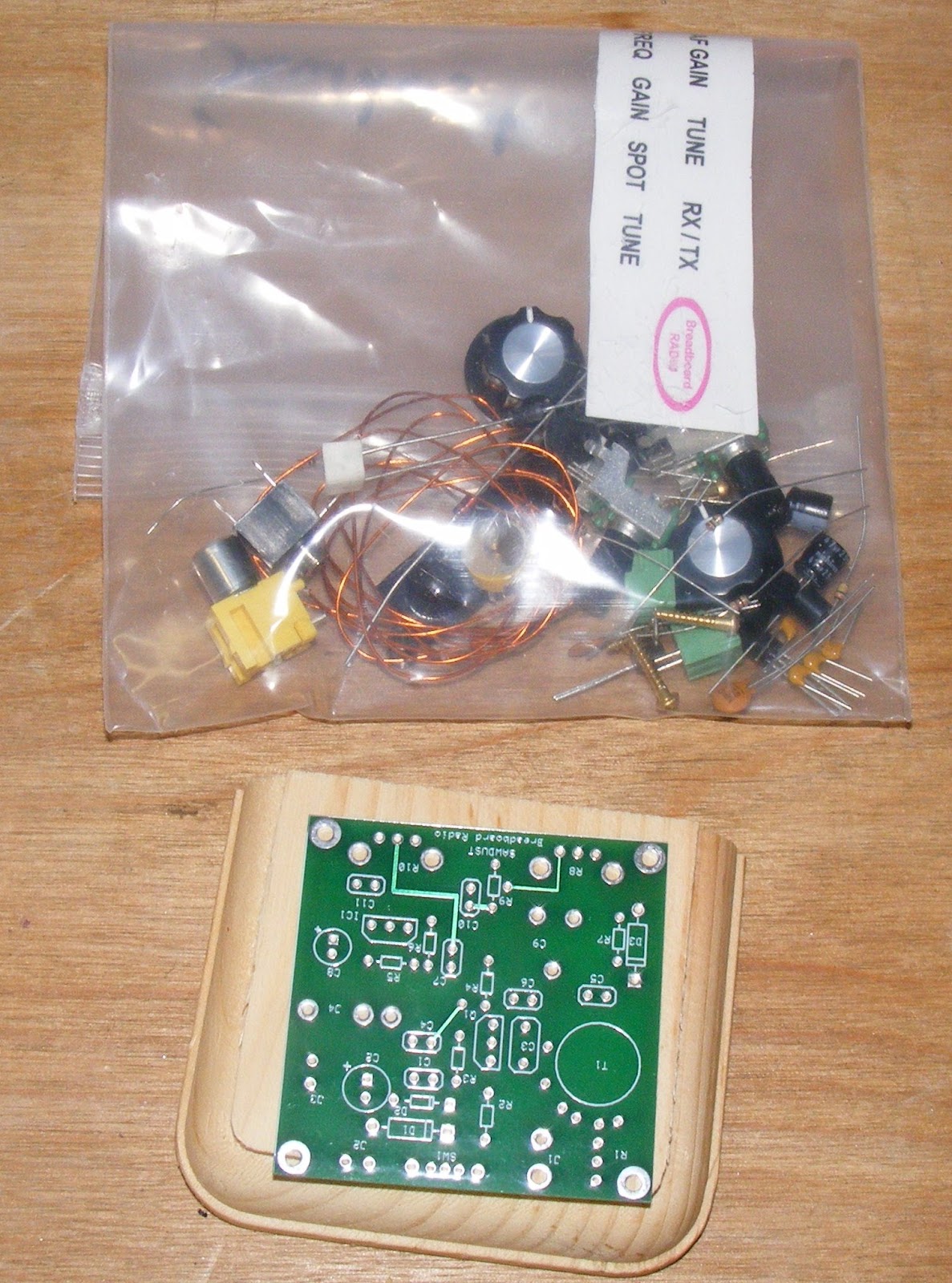
Kit as received with PCB, base, and bag o' parts. (Knobs included!)
Radio base in keeping with Bill's woodworking theme
Not an alien but the main coil. It is imperative that winding instructions are followed!
The main coil -- in situ
The alien reaching out for a victim?
Finished underside of board.
Finished top side of board. Note screw connectors.
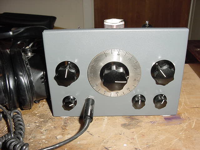
Finished kit - top left view.
Finished kit - top right view.
Finished kit - top straight on view.
Finished kit - well, you get the idea.
Anyway, there are several more points to make before closing this out. Firstly, read the freaking manual! O.K.? So, read it again and again and again..until you are familiar with it. I breezed through the instructions because I was the smartest guy in the room and I made a couple of errors -- fortunately not serious.
Be absolutely certain that you follow the coil-winding instructions to the letter! I did not at first but, before putting the coil on the board, I double checked my work (and the instructions) and discovered that it is important to wind the turns on the coil (there are three separate windings) in a certain direction or the radio will not work.
Also, those 1/8th watt resistors are mighty small and it is hard to read the color stripes -- SO BE SURE the resistor you are mounting is correct. I confused the 47K resistor for the 470K (or something) and I heard nothing when I put the coal to the radio. Extracting and swapping the resistors destroyed them so I dove into my junk box for replacements. (I only had 1/4th watt resistors but they could be mounted vertically on the board just fine.)
Oh, and these cosmetic issues: your friend, the genius, did not read the instructions and tried to peel the labels off their backing with no success. Then I found out that they were decals (just like the models you built as a kid) but it was too late. So, I cut the the remaining decal labels (I still did not have a clue) and glued them to the base after I finished it with some Danish oil I had on hand. I let it dry in the sum for about two hours and coated it with some Krylon clear coat and it turned out just fine.
When all was ironed out, I tested the radio and found that, once aligned and set, it could cover approximately 6,900 kHz through 7,120 kHz -- more than adequate for coverage of the 40 meter CW band. I will probably re-tune it to listen to the upper part of the band -- SSB or AM -- or even higher to hear the AM broadcast stations around 7,300-7,420 kHz.
But it is a great radio and fun to build. It cannot work miracles -- especially in my crappy location -- but when 40 meters is in (most nights), it's very sensitive using a short wire antenna and has a crisp, clear sound with plenty of audio to drive a set of headphones. And, believe me, this little project is one hell of a lot better than running down the errors and foibles of those hoary old QST articles.
Give it a try! Guarantee you will have a building and using it.
Just received my latest QST -- the January annual DIY issue -- and, rubbing my hands with glee, I sat down yesterday for a browse. It did not disappoint; loaded with a lot articles scraped form the bottom of the barrel that makes one wonder who really takes this shit seriously. Some samples and my crusty, salty comments:
A 3D Printed Key for Straight Key Night
One of those pillowy, brickish white things off a 3D printer. Looks like the key the Pillsbury Dough Boy would use. So, lessee, you drop several centabucks on a 3D printer to make one of these things..or, plunk down about $20-80 for a vintage J-38 and do SKN in style. Hard choice.
Using Unmodified Command Set ARC-5 Radios on the Ham Bands
The article concedes that the unmodified versions of these "command a significantly higher price than the modified ones". Yea, have you been out to ebay and seen the criminals sticking up the public for MilSurp gear? And the chances of finding an unmodified command set at a swap are slim and none. And "slim" is outta town. Plus with the unmodified ones, you have the dubuious pleasure of all those rotten, leaky old beeswax caps to deal with. You know the ones that double as 250 KOhm resistors?
Pass.
The Double-Nickel QRP Key
..another of those tin-snip-and-bolt-together beauties that are of dubious value because they have no weighted base nor tensioning/space adjustments. Again with the eBay vendors who sell decent products at a reasonable cost that are much more able to cope with my epileptic fist.
Desk Microphone Power-On and PTT Indicators
Mod your high-priced Icom SM-2D with a PCB and NPN-toggle device that turns on two small LEDs in the base of the mic when (1) the power is on and (2) you are yammering away with some other dolt on 14,275 KHz about the neat mod you made to your mic.
Like John Wilkes Booth once said, "Useless, useless."
Done in One: Battery Backup for your Wall Wart
Subtitle says it all: "Ride through the line interruptions with this handy device."
Wonder if these guys have ever heard of, ummm, oh, I don't know, running your station off of a battery in the first place?
You Too, Can Work 630 MetersAn article form one of the FCC-authorized hams allowed to experiment on 472-479 Khz wherein he advises that he scored a backup JRC NSC-17M transmitter from an auction of stuff from a commercial ship. Of course, like unmodified command sets, we have these things floating around all over the place.
..so, to avoid the rise in the subscription rate (and save about $50), I renewed QST for three years.
There's a guy on You Tube who is possible THE SMARTEST, MOST INTERESTING ham/electronics whiz I know. O.K., there are several - like W2AEW, etc., but I am absolutely aghast at Paul Carlson's range of knowledge, the projects he undertakes, his incredibly useful repair videos, and the absolutely Gothic work shop he has made for himself.
And, of course, I mean that last point in the nicest, most envious way. His regard for old-timey electronics and the care that he puts into his repair videos teaches one both respect for the heritage as well as traits and skills not apparent in the usual slap-dash, stumble-tongued how-to productions. (That would include, of course, those crippled, one-minute silent movie specials your truly puts up.)
Anyway, that said and in order to give you an idea what I am talking about, here's Paul on a venerable Tek scope:
..and for good measure, here's a tour of his lab:
(I can just hear the struts and cables groaning under the weight of those lovely, old instruments.)
I was not mindful that his B&K curve tracer had a provision for comparing two devices -- essential when matching transistors -- but called attention to the gimmick I built to do same. Of course, mine is rather limited to TO-92 and similar packages; one of those massive power supply pass transistors or an RF power amp device would need shoe-horning in. What hell, waddya want for a Sunday afternoon at the bench and idle hands!
It was designed for my Tek 7704A 7CT1N curve trace plugin and it's pretty straight forward as the pictures below will show:
It should be explained that the machined 8-pin DIP socket is mounted on a little board by the QRP-ME folks. (They make an extensive assortment of these useful little gadgets for Manhattan construction. Click here to see their basic squares and then walk back to see their other products.) Aside from that, Hoovering up the 2x3 pole switch might be an issue but easily had off eBay or a local electronics supply house.
If you view Paul's transistor designation tutorial (recommended), then you might think that the EBC versus ECB might be a problem.
Not so, anchovy breath!
Here I ripped off the socketing from those cheap DMMs where they have four holes marked EBCE. You will note that it's only a matter of slipping a 2S TO-92 package down one notch to get the correct connections. Also note that I color-coded the connector wires and the E wires are green. Note that both go to the last pole on the switch.
(I guess that's colour-coded for those in the Great White North. Paul is Canadian and I want him to feel at home.)
I'd post A/B pics of the curves but that'd get redundant.
Oh, and one final comment: Paul is the spitting image of my middle son, Erich. And that's a compliment as both are handsome and both smart as a tack.
The other day I had the distinct pleasure of attending the Orange County Amateur Radio Club auction and it was no ends of fun. Aside from benefiting the club with some shelf detritus ("One man's trash is another man's treasure"), I was able to repopulate the empty space with some stuff that i could not possibly exist without.
Chief among them -- and truly a treasure -- was this J-38 Morse code key. It is identical to the one I used back in the days of yore when I was pounding brass under the call sign WV6KJK. It cleaned up real nice and is like new. Enjoy:
I have a couple of "kits" I have compiled that are the old Novice crystal controlled transmitter and regen receiver and I have it in mind to build up an authentic 60s Novice station as a kick. Hell, maybe even use it to work SKN a year or so from now.
I am going to indulge in some wanton and probably unjustified ranting here and, with it, cast slime and aspersions on two guys who post You Tube videos that drive me to drink. But before I go any further, I will post them here and at least give you all a chance to crack a bottle of Jack as well:
The first is by Dave Jones over at EEVBLOG:
..and the second is by M. J. Lorton:
So, a caveat and then my complaint: I am a complete ninny when it comes to electronics and these two gentlemen can run rings around me in terms of knowledge and experience. That said, both are off-putting because they do not construct too many videos that help the average twit like myself. In fact these two are nothing more than 45-minute brag tapes about how Dave Jones scored his voltage reference for a song from some poor, unsuspecting clod at an Aussie swap. Don't even get me started on Lorton who manages almost one hour lisping his way through minute-by-minute temperature changes in his workshop. (And this is the last of six similar videos on the subject. Get. A. Life.)
Paint, drying, etc.
So, that's this got to do with anything? Well, I scored an HP 3468A off eBay for a modest price and was looking forward to incorporating it onto the bench as a reference because it was more accurate than all of my other instruments. Or, as Juvenal once famously said:
Quis custodiet ipsos custodes?
In doing research on my scored treasure I cottoned to the fact that this unit uses parameters stored in CMOS memory to effect its accuracy. Basically, the instrument measures what it measures and then offsets or digital differentials are applied to the measurements to show up on the display. Again, these are stored in CMOS memory circa 1980s and that was volatile. If it lost power, the RAM contents vanished. In order to retain the memory, HP designed a 3V Lithium battery backup that lasted about 10 years.
Well, that's all well and good an idjits like myself open their treasures up, slap a DMM on the backup battery, read 3.12V and think all is well. Sadly, a Lithium battery has a life profile that looks like a ball rolling off a table. After ten years, you're living on borrowed time.
(This was the deal with my old Icom IC-745. When it lost its mind, Mother Icom had you by the short hairs to reprogram the radio. Fortunately, the Piexx folks came along with their non-volatile RAM and saved the day.)
So, casting about, I found a tremendous gentleman -- Mr Modem Head -- who did a treatise on restoring a 3468A and replacing the CMOS backup battery. Fearing a day of reckoning, I studied both posts assiduously, got a replacement battery form DigiKey, and last Sunday afternoon I did the surgery.
Well, the operation was a success but the patient died! When I powered the unit up after the solder cooled, up came the infamous ERROR 1 message on start-up:
I swear by all that is holy, the backup battery was strapped with 3.25V at all times. I followed the procedure to the letter. But, alas, I crapped out, rolled snake eyes, busted, came up with three peach pits, etc. So now my treasure was only as good as the other DMMs I had lying around and I was off searching for how to calibrate it myself using a Voltage Standard DMM Check, the HP service manual, and my wits.
..well, the DMM Check and service manual at any rate.
By the way, Mr Modem Head's blog is everything that Wanker and Motor-Mouth Jones is not. It is artfully done, contains useful information; true wit and wisdom. Sadly, current events (life, responsibilities, etc.) conspire to keep Mr Modem Head from to many recent posts but he is a roll-up-your-sleeves electronics hobbyist who shares his project efforts in a stunningly beautiful style superbly laid out on his blog. (See links above.)
..all for the common man without benefit of $20,000 instruments or being knee-deep in prime Fluke or HP surplus.
Anyway, the outfall here is that a calibration shop was located who would redo the parms for $65 and my HP is headed for Medford, Oregon as we speak. I will keep you apprised.
My Tek 485 had been sleeping on the shelf and I needed to take it to a friend's house to help him debug a problem. Checking it out before I left, I found it did not light up -- no power, to pilot light, no trace, nothing.
So, with the help of my friend, Dick, WB6JDH, I took it apart and did a preliminary visual on the back plane, the line board, the switcher board and the PS board. The two 430-ohm resistors (R1812 and R8113) were burnt out so I replaced them with two 2-watt 470-ohm resistors on the line board.
All else looked fine. After cleaning out some carbon and dust, pulling the "start" transistor and then the "stop" transistor on the PS board and bringing the unit up on a variac with each, we got the power supply to work -- but experienced some smoking and burning during the process.
Cleaning out further carbon and burned areas revealed no seemingly bad components so we brought the unit fully up under power and it seemed stable. However, attempting to view a trace on the scope revealed that the vertical position controls did not work and I was unable to get a dual trace. I was pretty careful with the setup and triggering so I do not thin thee was a cockpit error. Another anomaly was a distinct PS snapping when the "ADD" button was pressed.
Here's the video:
Resolved!
A tantalum cap on the A7 board (near U650 and the 15V test point) shorted and took out the associated RF choke. We swapped the A7 board with one from a donor 485. Turns out that one was bad as well. Q374 and Q384 were both bad and were replaced with matched 2N3904s. Was easy to do because most semiconductors are socketed on that board. But that was karma because removing and replacing the A7 board WAS a bitch! The delay line was soldered on and a semiconductor on the board was bolted on a heat sink to the frame below. Getting its leads through the two holes in the sub-chassis was a delicate operation -- especially on a 100-degree day with 90% humidity.
I deserve NONE of the credit for solving this problem! Dick, WB6JDH, [literally] sweated through the debugging process and suggested we swap boards from the old donor unit. I just dd the donkey work and took copious notes.
I also treated us to burgers and dogs afterwards.
Resolution Resolved
Actually, the resolution was a false positive and the malady returned. (And, truth be told, who's to say it won't return in the future?) But, in tracing the origin of the horizontal position controls back to their source on the power supply board, I found all of the components in each of the position controls to be within spec and performing correctly. However, it was noted that the cable plugs along the top of the PS board were unseated and, after re-seating them, the scope seemed to function correctly. So, as I said, the problem might re-occur but at least I'll know how to troubleshoot it. Stay tuned..or don't!