Tuesday, February 1, 2022

Cam and Dick's Kortge Scratch Built 2N2-40

A couple of years ago, Cam Hartford, N6GA, left us and we still remain saddened at his passing. In the wake of his departure, Dick Palmer, WB6JDH, and I and a couple of other friends of Cam helped to "parse" the ham radio component of his estate. In that effort, Dick came across a remnant of Cam's industry, a partially built Jim Kortge 2N2-40.

Dick -- ever the industrious breather-of-life-into-things ham that he is --  completed it and got it working. He then thoughtfully gifted me with it for which I am very grateful. This has always been on my bucket list to build one of these and Dick's thoughtfulness has not displaced that project. And it certainly makes life easier that I have a working edition of that radio to guide me. 

Anyway, here are some pics for your edification.


Enjoy!


Sunday, November 28, 2021

Tektronix 7D14 Fix-Up Part V - So I rewired it!

After going through considerable testing and reviewing a lot of marvelous advice and help from the Tekscope group, I have come to an interim solution. Like Tim Allen advised: "So, I rewired it!

Seriously, I was chasing my tail and came to a dead end for the moment. The problem was the overheating relays but I could not find the reason for the overheating except that possibly ALL the relays were defective. (Which I doubt.) If there was some deep-seated problem other than that then I would troubleshoot it another day. Meantime other projects awaited. 

From the previous posts on this you will note that I discovered that cooling the plugin board allowed it to operate hours on end without faulting on the display. So, succinctly, I was able to locate a source of 12 VDC (from the other existing fan board) and bolted in a three inch muffin fan I had lying around.

The burn-in testing with all covers and running in a "normal" environment failed to fail, if you will. It ran for eight hours. In fact, I ran BOTH of the frequency counter plugins I had -- the 7D14 and 7D15 -- in the same unit and was counting input signals to beat the band.  

Below are pictures for your (ad my) reference.

Enjoy.


Monday, November 22, 2021

Tektronix 7D14 Fix-Up Part IV - Relay Switching


To continue where I left off, I still have not arrived at a resolution but have come to a certain stopping point and wanted to write up the results so far and not leave this hanging. Since my last comment, further analysis/testing was done on the relay switching "logic" focusing on the voltages taking the following steps:


Here are the voltage measurements based on the AC/DC and INPUT SENS switch settings:

 And, for reference, here is the pin-out for the  SPDT and DPDT relays:

At this point I cannot explain why the relays ALL are hot to the touch. A friend tells me that his 7D14s' relays do not get hot at all. Since these relays are not commonly available, the only option is to score some from a parts unit and substitute them to see what happens.

I will probably be evaluating the switching with respect to the signal path. That is, speculating where the signals should be present depending upon the INPUT SENS switch selection, etc.

Stay tuned.

Sunday, November 14, 2021

Tektronix 7D14 Fix-Up Part III - The Heat is On!

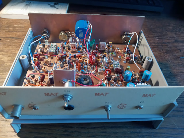
I got a little closer to understanding the problem today. But first a brief explanation of how I have been testing this plug-in. This is an explanation I provided one of the respondents to my thread re the circuit behavior. Of course, a more complete description if available in the 7D14 service manual. SO, here goes:

The 7D14 has two inputs: the TRIGGER SOURCE, which is introduced to the counter from pins 20A/20B of the plug-in connector. The other input is the "CH A INPUT" BNC on the front panel of the counter. The counter selects these by means of the "INPUT SENS" [sic] switch on the front panel. It has six positions: 50Ω 1V and 100mV, "TRIG SOURCE", 1MΩ 100 mV, 1V, 10V going clockwise on the face.

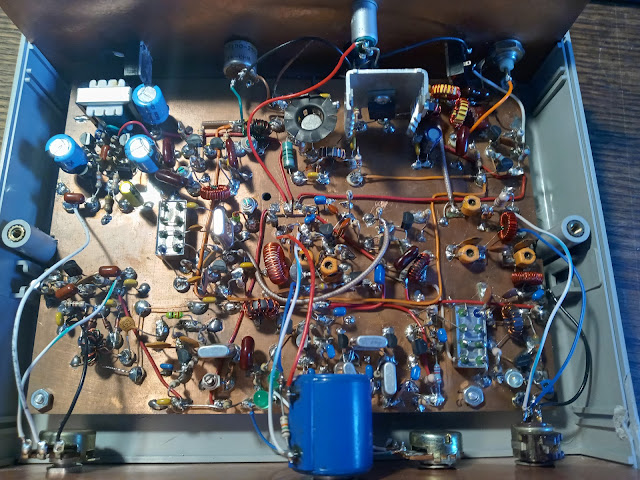
The 50Ω and 1MΩ positions activate/deactivate various relays to run the signal through resistor pads and to achieve the designated attenuation (with capacitors to compensate for high frequency signals). The signal ultimately is introduced to a push-pull "Input Amplifier", is processed, and ultimately is passed on to the counter logic circuit. The boundaries if this amplifier are a pair of matched FETs (DUAL FET package) of Q130A/Q130B and -- for our purposes -- Q147 and Q247.

When the "TRIG SOURCE" position is selected, the signal from the 20A/20B connector pins is routed through an energized "Trigger Source Amplifier" comprised of Q216 and Q218 whose output is sent to the Q130A/Q130B FETs of the push-pull amp described above.

Thus, I chose to measure the signal at the base of Q216 -- the input to the Q216/Q218 amplifier -- as one point and the aforesaid Q147 -or- Q247 bases as the other point.

I ran the test until the counter failed (displayed zeroes) and noted that the bases of Q147 and Q247 lost the signal that appeared there when the test started. The signal at the gate of Q130B was still extant. So I moved the second point "inward" and did a rinse and repeat.   

This was done until the second point was the gate of Q130B where I noticed the signal disappear. To make a long story short, I then went through the "Input Amplifier" to determine that it was working.

So here we are. I am convinced the push-pull amplifier is working and I am convinced the "TRIG SOURCE" "Input Amplifier" is working The only question I had was the one I posed in one of my comments above about the overheating relays.

Per a recommendation, I swapped the relays as described but saw no difference. Also, I remain concerned because the other relays were hot tot the touch as well which does not comport with my friend's experience.

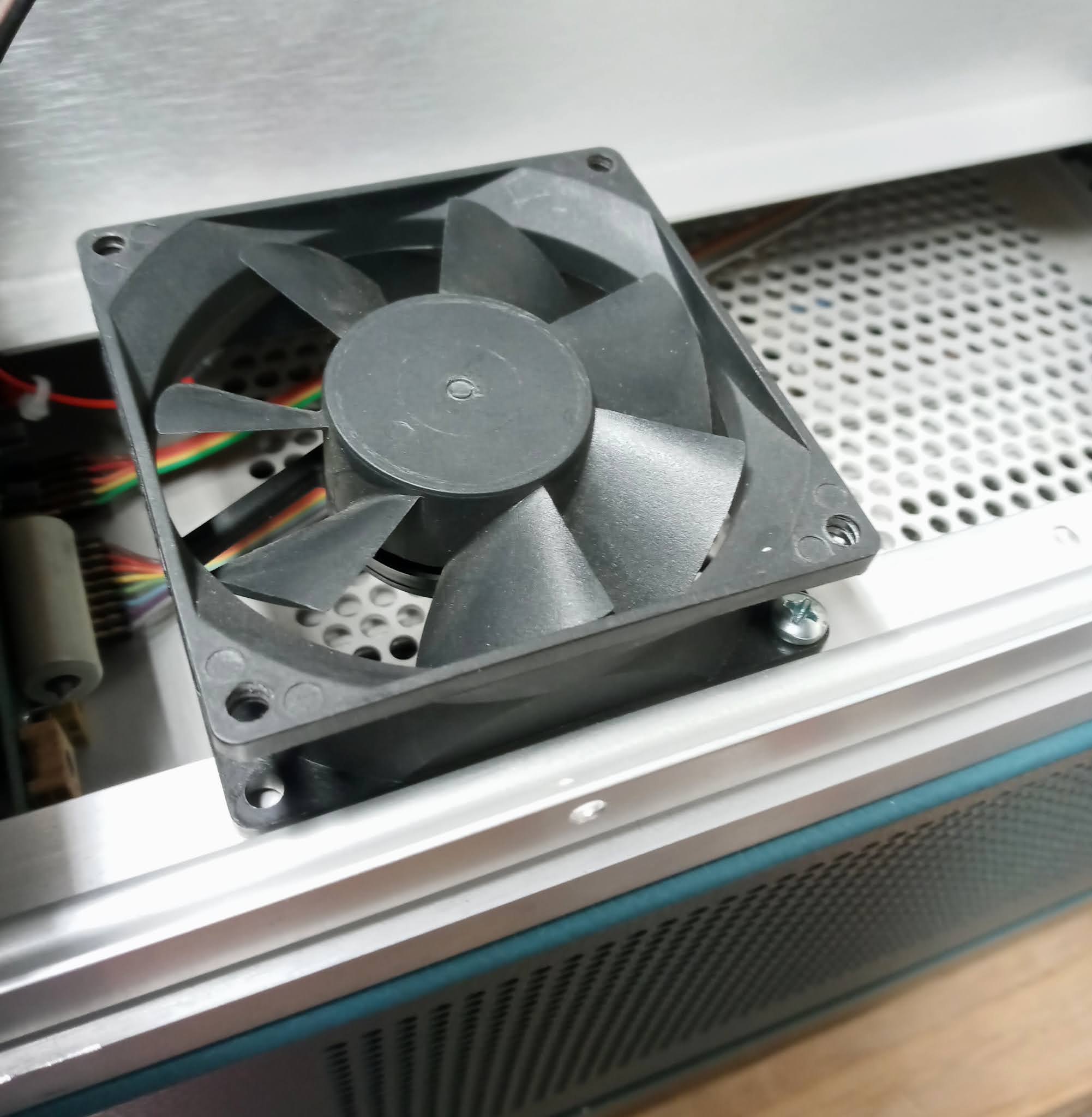
Based on the above, I kicked the can a little further down the road here on 7D14 here. Today I embarked on a little experiment. Still puzzling about the relay heating question, I set up the unit to test in the cool of the morning. (We have been having a three-day desert Santa Ana wind condition and the bench area was a little warmish. It was cooler today.)

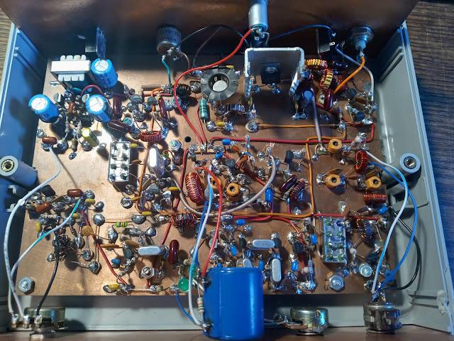
I propped a fan up to the side of the unit and fired it up. Succinctly, it ran for six hours rock-solid, dead on perfect without any problems. Moreover, the three relays on the front of the board that had heated up in the past were merely warm. Interesting to note, however, the two relays at the back of the board -- K125 and K252 - were hot.


So I am forced to conclude that something is causing those relays -- the SPDT ones, at least -- to head up. I mostly understand the circuit (as I explained to Harvey) but do not know why the relays are heating. I do know there now is a correlation between the plug-in failure and the excessive heat.

..and all this with a Rigol DS1102E sitting on the bench to boot!

Friday, November 12, 2021

Tektronix 7D14 Fix-Up Part II

 So far, despite a visit and some serious time with my good friend, Dick, WB6JDH, we were unable to unravel the mystery of the fading 7D14. We covered a lot of ground but have not yet unlocked the puzzle.

Dick discovered some ambiguity between my unit and the manual documentation and found that the Q218 (151-0271-00, the PNP transistor) was actually in BACKWARDS. Reversing it caused more correct signals to be observed for a longer time. We also discovered ambiguity in the manual documentation between the pin-outs Q130A/Q130B (151-1031-00, the DUAL FET in the TO-71 case) and the diagram in the book. (Will be detailed in subsequent "Chinese Checkers" post.) This led us on a course of substitution -- Q218 was replaced with a 2N3906 and the dual FET was replaced with two J310 FETs. These seemed to work great for an hour of two and then behaved as described and then behaved as I discussed below.


I piddled around a little after Dick left and managed to be present when the TRIGGER SOURCE signal crapped out. I quickly switched the signal to the CHANNEL "A" input BNC and saw that the counter continued to work properly when the INPUT SENSE switch was switched from TRIGGER SOURCE to one of the attenuator positions (as we discussed). I then rigged a "T" connection of the generator signal to the 7A26 CHANNEL 1 input BNC and the CHANNEL "A" BNC such that when the signal died from the TRIGGER SOURCE position, I could quickly switch over to the CHANNEL "A" input.


As time permitted yesterday (tiptoeing around normal duties), I experimented with this setup of switching quickly back and forth between the TRIGGER SOURCE and the CHANNEL "A" inputs. I noted that the counter did not fail in a similar manner as it had in the past. Whereas the display would "fade to zero" in a matter of seconds, now it just grew inaccurate, displaying "20.0xxx" where the "xxx" digits would remain unsteady. When it was switched to the CHANNEL "A" input, the display would revert to a rock solid "20.000" MHz.

I turned my attention to the relays and found that the K106, K101, and K100 units were very hot to the touch but K103 was not.


This morning, I set up a test of the unit again and, while it lasted a full three hours plus, it again failed. This time BOTH the TRIGGER SOURCE and the CHANNEL "A" input displayed zeroes.

The 7D14 manual describes this circuit nicely but I am still puzzled if sticking/malfunctioning relays could cause the problem I am having with this plug in.

Sunday, November 7, 2021

Tektronix 7D14 Fix-Up Part I

In starting out on this, I compiled some notes on the 7D14 and its misadventures. I believe the problem is in the "front end" where the signal is processed from either the "A" channel BNC or the "B" channel internal routing from a vertical amp. The 7D14 service manual bears reading -- particularly the circuit operation description. Here are some preliminary testing observations:

(1) The symptoms are that the counter will display the frequency accurately for a while -- about 20 minutes to one hour -- and the display will wilt to zero.

(2) For a while, I was able to input the signal (60 MHz - same as input to the 7A26) to the "A" channel BNC but and thought I had "isolated" the problem. But not so much anymore.

(3) I chose to start at R222 as it is the input to the input amplifier stage -- Q130A/Q130B, the curious dual N-channel FET -- to determine if where the signal was getting dumped. Starting up the cold 'scope, I saw the signal there at approx. .091 Vpp and even after the 7D14 stopped displaying the frequency, i.e. displayed zeroes, the signal was still there albeit somewhat diminished at .041 pp.

(4) The subsequent point immediately after -- Q132/Q232 base, Q141/Q241 base, and Q136/Q236 base -- all showed no or erratic signal.

The voltage measurements below are the signal measurements from the scope -- though they are little more than the numbers behind #4 above. I appended the voltage measurement pictures.

One more thing I gotta tell you is that I am no fan of the Rigol DS 1102E scope I recently got. I am absolutely unable to operate the thing! The trace is fuzzy and erratic but it's probably me but it still makes me no fan of digital scopes -- so far!

SCOPE TEST MEASUREMENTS
 

MEASURE            7D14               7D14
POINT           RUNNING GOOD       CRAPPED OUT
R222             .092 Vpp             .042 Vpp

Q132 base        .048 Vpp             NONE
Q232 base        .048 Vpp             .027 Vpp

Q141 base        .310 Vpp             NONE
Q241 base        .260 Vpp             NONE

Q136 collector   .300 Vpp             NONE
Q241 collector   .230 Vpp             NONE


Thursday, November 4, 2021

Tektronix 7D14 Fix-Up

After having repaired my 7D15 freq counter plug-in (a questionable cap, bad solder joint, and some pilot error), I am turning my attention to a 7D14 that is flaky.  Below are the facts.

(1) Problem is that the 7D14 stops displaying the frequency correctly -- i.e., displays all zeroes -  when the signal is sourced from a vertical amp. I have tested with a signal input from the unit's front panel BNC and it does seem to not fail.

(2) The problem seems heat related.
(3) The set up is as follows:
    (a) Scope is 7704A.
    (b) 7A26 in left vertical slot.
    (c) 7B92A in horizontal slot A.
    (d) 7D14 in in horizontal slot B.
    (e) Vertical mode LEFT.
    (f) Horizontal mode A.
(4) Other settings per 7D14 manual troubleshooting/calibration set up.
(5) Signal input to Channel 1 on 7A26 and adjusted to AC, set to display and trigger on channel 1.,
(6) 7D14 set 10 ms, Trigger Preset, 525 MHz, AC, TRIG SOURCE, and frequency is displayed correctly on CRT.
(7) After about 1-2 hours, the frequency display becomes erratic and then displays all zeroes.
(8) Removing the side panels on the scope and the plug-in and blowing it with cold air causes the frequency to be displayed properly.
(9) Leaving the plug-in exposed (no side panels) causes it to run indeterminately longer without failing. (That is, I have let it run several hours without failure.)
(10) Similarly, I have set it up to read a signal input from the CH A INPUT BNC in the 7D14 front panel and -- even when covered with the side panels -- it seems to run a long time and not fail. (Similarly, I have let it run several hours without failure.)

In looking at the manual and reading the schematic and notes, I am guessing that the vertical input from the 7A26 arrives on pins 20A (+TRIG IN TO T870) and 20B (-TRIG IN TO T870) and, accordingly, I have begun to snoop through schematic <1> CHANNEL A SIGNAL CONDITIONING but sense that I may be a little off. I thought I'd document my fix here if I am successful. 

Below are some pictures of the two PCBs in the unit in no special order. If you click on them they will enlarge for a more detailed view. Subsequent posts will track my progress and I'll also mark up the photos below -- if needed -- to highlight areas of importance involved in my problem resolution.

High Frequency Board


Logic Board