 When family, work, and the USAF Auxiliary allows it, I frivolously waste time on ham radio and electronics projects and, when doing so, I am in one of two modes: gathering projects at swap meets or building, fixing, or operating the treasures I haul in.
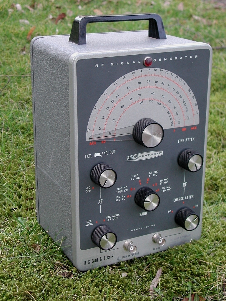
 But, alas, my hunter-gatherer skills far outstrip my builder-operator skills and I have built up quite a backlog of these projects. To shame myself, I order my "acquisitions" into a FIFO list so that there is some throughput at least and the scenery in the workshop garage changes over time. Anyway, somewhere back in the past six months, I went on a jag and started accumulating Heathkit IG-102 signal generators. You know, these beasts on the left there. (For that matter, I always go on these jags. As Dennis Kidder, W6DQ famously says, "Why buy one of something when you can have two at twice the price?" The VTVMs were the result of such a bender.) I amassed three of these generators, two in good shape and one having no power cord and generally requiring more attention. Well, last weekend, as they were gathering dust on the shelf, I decided it was time to act and started in on refurbishing them.
Now, for those looking for a low-end signal generator at a reasonable cost, the IG-102 is a good one. It's about $35-75 (or more) on EvilBay or $20-50 (or more) at a local electronics swap meet. (I prefer the latter venue because of the cheaper prices and the fact that you can eyeball the product INSIDE and OUT.) Also, the fact that the entire manual can be found as a .pdf (think mods.dk) is a definite plus as the build "how-to" is definitely more informative than the troubleshooting chart in the back of the manual.

As for refurbishing the units, I rescued the two and breathed life into 'em in a far shorter time than I thought it would take. Initially, both did not produce any RF out whatsoever. So, after poring over the schematic for a while, I poked and prodded from where I thought the RF should originate and was delighted to find a signal. I proceeded to follow it to the RF out connector but I lost a little bit somewhere between the plate of the pentode side of the 6AN8 and the wiper of the fine attenuator pot. The rest of the RF fled on the input side of the course attenuator switch.
Judicious application of contact cleaner at various points on that path materialized the RF at the output connector and we were in business. One of the signal generators had a "lumpy" fine attenuator pot so I replaced it with a 10 KOhm one I had lying around. (The original was a 3 KOhm audio taper jobbie.) The 10K worked fine; it was a little tight but, with practice, I was able to set my signal level right enough.
The only problem was that I only had one set of tubes so I ordered another 12AT7 and 6AN8 off of eBay. Just to let you know, they ain't cheap and, surprisingly, the 6AN8 is a little more dear than it's cohort. If you want to rebuild one of these machines, budget another $20 for the tubes if yours are shot or missing. Also, here's a re-cap of the recommended debug steps:
(1) Don't hesitate to clean the switch contacts on the attenuator pot and the band switch (where the coils are).
(2) Trace the obvious signal path from the grid of the pentode half of the 6AN8 through the fine attenuator pot through the coarse attenuator switch. If you are using a scope, mind the DC on the plates of the tubes and such. There are convenient DC blocking caps where you can pick up the RF if it is available. One prime spot would be at pin 8 of the 6AN8 as I recall.
(3) You might find the fine attenuator pot "lumpy" -- it can be replaced by a 3 KOhm pot or a 5 KOhm one or even 10 KOhm pot -- which I used on my "keeper" unit.
(4) Replace those useless mic connector plugs on the chassis with BNCs. It's very easy to do and makes your unit more compatible with coax links you might have laying around.
The remaining unit of the trio lacks an AC power cord and will probably end up becoming "transistorized". I actually was going to do this with all three, except the first two work so great when refurbished, I did not want to go to the extra effort. (If it ain't broken, don't fix it.)
In any event, to convert this unit, I'll have to strip out the AC power supply and the tubes and replace the latter with a pair of MPF-102s each. When done, it will be powered by a 9V (or 12V) battery. Notes on the project (it came from the May 1978 73 Magazine) advise soldering the MPF-102s to the actual tube socket lugs underneath the chassis. But, I am thinking about getting some tube-pin-diameter copper wire and stick those into the appropriate tube socket pins and then wire the JFETs to the copper wire. That way, if I blow up a JFET, I can pull it and insert another.
Looking at the pin-outs and how one wires the drain, gate, and source, I surmise that the two JFETs will face each other and the pin-outs will be:
12AT7
FET #1 - 1=Drain, 2=Gate, 3=Source
FET #2 - 6=Drain, 7=Gate, 8=Source
6AN8
FET #1 - 1=Drain, 2=Gate, 3=Source
FET #2 - 6=Drain, 8=Gate, 9=Source
..but DOUBLE CHECK; I could be wrong!
No comments:
Post a Comment