Friday, February 22, 2013

Revisiting N6TWW's Calculations..


In a preceding post, Mike, N6TWW, discussed the calculations he made in order to develop a phasing harness for a couple of VHF antennas. I borrowed on his numbers to further ingrain this poor boy's TDR technique.
(1) Speed of light = 186,000 miles per second.

(2) 186,000 x 5,280 = 982,080,000 feet per second.

(3) 982,080,000 / 1,000,000,00 = 0.98208 feet per nanosecond.

(4) 0.98208 feet = 11.78 inches.

(5) Light travels 100% in free space but travels only as fast as the velocity factor along a cable.

(6) The velocity factors of popular cables are:

      CABLE    -  VF
      RG-8     - .66
      LMR-400  - .85
      RG-8X    - .84
      RG-11    - .75
      RG-58    - .66
      LMR-195  - .83
      RG-59    - .82
      RG-62    - .84
      RG-174   - .66
      RG-213   - .66
      RG-214   - .66
      RG-217   - .66
      RG-218   - .66
      RG-316   - .79
      RG-400   - .695
      LMR-500  - .85
      LMR-600  - .86
      1/2 HARD - .81
      7/8 HARD - .81

(7) I got 2 hunks of cable I want to determine the length of. One is a long piece of RG-8X and the other is a shorter piece of RG-58. I have another hunk of coax that I want to verify the velocity factor of.

(8) For the longer hunk of RG-8X, I assume that the velocity factor in 84% so that means that when an electron travels through it it's only going 84% as fast as its cousin in free space. Consequently, it is traveling 84% of 11.78 is 9.98952 inches. So let's say 10 inches for grins.

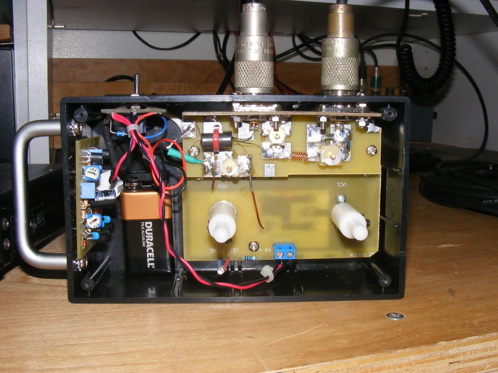
(9) I lashed up the scope and the function generator like these two lads did and found that the RG-8X cable's out-and-back trip was 2.4 divisions at 100 nanoseconds per division. So 100 x 2.4 = 240 and half of that (only want one-way) is 120 nanoseconds. Thus, the cable is 120 x 10 inches or 1,200 inches long. Obviously, 1,200 inches is 100 feet. (Do I really have to?) And, guess what, that's what the guy at the swap meet sold to me: 100 feet of RG-8X.

(10) The shorter hunk was 1.6 divisions at 100 nanoseconds which works out to 160 nanoseconds. The one-way time, of course, is 80 nanoseconds and, since it's RG-58, the distance traveled in a nanosecond is 11.78 x 0.66 or 7.78 inches. So electrons traveling 80 x 7.78 inches or 51.8 feet. Let me get a tape measure and check that number.

(11) Now for the third hunk of coax, I know it's 22.75 inches long and I know that it "scopes out" to 0.7 divisions and 100 nanoseconds. Half of this (one-way trip) is 0.35 x 100 or 35 nanoseconds and 35 x 11.78 or 412.3 inches or 34.36 feet.

But that's the distance in free space, and I know that the coax is 22.75 feet long. So the velocity factor would be 34.36 / 22.75 or 0.662107 or 66% -- which is what they say RG-58 should be.

Funny thing, that!
-72-

Probing the mysteries of 'scopes..

Here's the deal-e-o on scope probes:


..remember, this blog is for me and not for heavy duty PhD EE types. Sorry for my pedestrian pace.

-72-

Wednesday, February 20, 2013

Time Domain Reflectometry for the poverty stricken..

Munching my tuna fish sammich today at work and came across this:


..thought I'd store it away here for reference. Here's a practical application of this method:


Let's face it, I'm like a kid in a candy store. I am smitten with this application. Here's a variation on the same theme:


..graphic explanation for characteristic impedance and possible entre into the phenomenon of SWR? Lord, is this fun or what? I feel like one of those freaking apes at the monolith in 2001.


Ain't life grand?

-73-

Tuesday, February 19, 2013

RX2 Wrap-up..

Here's some pics just as I am buttoning it up after calibrating the unit. Lou's checkout procedures seem very cryptic at first but, after you become familiar with the operation it makes perfect sense. I plan on going back in and re-doing the unit just because I am an inveterate tinkerer. And, let's face it. I need something to do until the RX1 arrives.

"Rex, the Wonderbridge" (the RX2) along with my FT-817  ~~ affectionately, "Tex".
(I actually used to own a Sangean receiver, by the way.)
Close up internal view.
Buttoned up, next to Tex, ready for business.
Close up of the cabinet and dial.
Rex and Tex, mates for life!
The dynamic duo about to elicit some dark secrets from Mr Coax.
The pair attracts the attention of Mr Palomar, who is contemplating retirement.
Left side of the bench and the Ten Tec I am trying to breathe life into.
..and we fade out with a view of the clubhouse, our hero shutting down operations for the day and contemplating the blissful prospect of a cool one and the pleasant company of Mrs K6WHP.
-72-

Meanwhile, back at the ranch..

I guess I am like a kid in the candy store what with the wonderful things we can lay our hands on in amateur radio. Despite my seemingly wandering eye, I am having a blast with Lou's RX2. I took it to a ham radio swap meet yesterday (no pictures, sad to say) and endured the usual cretinous remarks like, "why should I use one o' them thangs? Ah gots me a MFJ 259!". Of course my churlish responses sort of morphed into, "yeah, and I'll bet you use a pocket calculator too, instead of a perfectly good slide rule!"

Jeeesh! Some people just do not get it, do they?

Anyway, with all of the components assembled, it's time to put them together. Here's a bunch of snaps with the components just prior to bolting them in and tuning the little beast up.


Nothing remarkable; just different views. You might want to check out the power switch board. Lou uses a rather simple board to anchor the power mains and the switch. Also note the LED incorporated into the RX2.  The first thought it that it will drain the battery plenty damn quick but, as a person who has left my Palomar Engineers noise bridge on more times than i care to mention, I can live with this.

Also, a follow-on comment by Lou about my trimmer inductor. He says I probably have too may turns on it to properly compensate the bridge for operation around 28 MHz. Maye so, but it tuned up nicely -- or so I think. I will be going back to revisit the initial calibration of the bridge once I get the hang of using it. I would not be surprised if Lou were correct.

-72-


Thursday, February 14, 2013

The RF board..

Now comes the fun. Take it slowly and carefully here and I recommend scrubbing RF board with alcohol and/or flux so the solder will lay down nice and smoothly with the slightest application of the iron. The traces here are huge patches of silvered copper and it's easy to build up mountains of unwanted solder and a bitch to wick the excess away. Also, the check-out/adjustment procedure requires soldering components temporarily onto these pads and then removing them. Inattention might lead to a mountainous mess.

Word to the wise. If you look closely, you can see where I was incautious with the solder on the back plane board and had to steel wool the excess away.

Also, there comes that moment of truth when you have to solder the RF board to the back plane board. Same caveat here: do not go crazy. "A little dab'll do ya."

Back plane, RF, and control board in place with transformer mounted.

Same; obverse view.

Yet more of the same from a different angle.

Here's the RF board with the components mounted

Yet more of same. See comments in this post about trim coil.

Sidelong view of RF board with mounted components

K6WHP luxuriates in his mighty efforts.

The whole magilla.

Lou provides you with the wire to wind the trimmer coil. He also provides some pre-wound springs. Here's my advice: use the springs. You will never wind a coil as neat as those springs. Also, about five or six turns should do the deed for the checkout.

Sidebar war story: I LOVE winding toroids and coils. They are probably the sexiest component in any kit. A long time ago, Doug DeMaw, W1FB, founded Oak Hills Research and they produced the OHR-100A and the OHR-500. The latter had a shit-pot full of toroids (about 20 or 30) in them and Dick Witske (who bought OHR from Doug DeMaw) apologized profusely to me when I bought the kit from him. But I told him I was on the verge of buying another one on the basis of the number of toroids.

Sure wish I kept that radio. It was all transistor; not an NE602 or LM384 in sight and quiet as the tomb. You'd tune across 40 meters in the evening with nary a hiss or crash until you came across a pure. clean CW signal. When I built mine and first turned it on, I thought the front end was dead until WB6JDH straightened me out.

-72-

The RX2 transformer..

This little beauty injects the "go juice" into the bridge so the radio can hear all the rack or the null depending on the circumstances. It's made wound on a binocular core ("Corpse" if you're Obama) and -- while daunting -- Lou's docs and pictures help you through the exercise. You just have to make sure you know where one winding stops and the other one starts.


The manual instructions has a picture with these starts and finishes marked on them. If you mind the pictures, you should do o.k. A ton of enameled wire is supplied with the kit but I had some "bare" enameled and some green enameled so I chose those to differentiate the primary and secondary windings.

I did have some red wire too, but I was getting a little "Christmassed out" and went with the bare copper look.

-72-

Assembling the RX2 backplane and control boards..

Our adventure continues with the "back plane" and control board assembly and mounting. Just to let you know, though, that the quality of the project box Lou provides -- like his other components -- is superior. It's a plastic box with countersunk lid holes and even screw covers. The only difficulty I found (and I am leaping ahead here) was that the box screws were self-tapping and tough to unscrew for subsequent noise bridge re-adjustment and battery changing. With the threat of stripping the screw heads imminent, I cast about the junk box for more substantial Phillips head machine screws that fit nicely and were more easily removed. Here is a sample with a screw cap:


Assembling the back plane and control boards involve the controls (variable cap and pot) and coax socket hardware. With the pictures and instructions and videos provided by Lou, the process is moderately plain sailing.

Mounting the cap and pot on the control PCB. Note nylon shafts in upper right of picture.

Closeup of control board and position of control tabs.


Positioning of tabs.

Soldering the control tabs.

Top view of control PCB before nylon shafts added.

Back plane board with the coax connectors.

Back plane and control boards mounted in project box.

Reverse view of same.
-72-

RX2 noise board assembly..

The first crack out of the bag, you assemble the noise board. It's a fairly straightforward process for a fairly simple board. Once assembled, you jury rig a power connection (even with a diode for reverse polarity protection), put the coal to 'er, and check out the noise in your receiver and scope.

"Parts is parts"

Finished board.

Jury rigged power connection with diode for reverse polarity protection.

Underside of board. Note soldered nut for attachment to project box.
-72-

Meanwhile, back at the ranch..unpacking the RX2 kit..

O.K., enough GDO porn for the moment. Let's get back to the VK3AQZ kit. Righty right right, me brothers!

But, before we do, I want to make a point about the editorial policy here. Firstly, this will be a family blog but I reserve the right to drop a few S-bombs once in a while. (Hey, were you sitting with me at my bench in the "clubhouse", you'd hear as much. Secondly, I take a lot of pictures of projects I do because I like to admire my handiwork. I am not going to bust my ass to make this blog a bleeding QST or CQ article layout. I mean, I got as much bandwidth here as the sodding Blogger folks want to give me, so I am going to use it. So we straight, podnuh?

Good! Now on with the show.

This first post on the building of the RX2 are pictures of the kit as you receive from Lou. As you can see, he gives you a lot of stuff! Enjoy.

Just unpacked from Down Under..

..note plethora of goodies that Lou provides..

..including "spare bits"..

..and here are the boards: backplane board, control board, RF board, and noise generator board.

Here are the controls, hardware and project box.
Note that my Palomar bridge got curious and came over to take a look.

All of the parts will eventually get organized into one of these project boxes I have.

..and, just for grins, here's the workbench in the "clubhouse".

The takeaway here is that Lou gives you more than enough stuff to bring this project off. He even provides solder and -- as I said -- multiple versions of his labels! Hell, he even provides you with the files containing the label artwork so you can design your own!

-72-

Wednesday, February 13, 2013

My Millen GDO Jones..

Whilst fabricating my RX1, my ardor for collecting and owning other instruments morphed into a serious Jones and has had one significant outfall. My collection of Grid Dip Oscillators has grown substantially and, while not near the magnitude, if I do not take care, my obsession may cause me to overtake N4XY's museum I do fear.

(A catty comment on Mr Tanton's collection: he could sure use a few lessons on web site design. Basically, it's like viewing the wonders of the Smithsonian Institute through a peephole in the front door. Not to denigrate his efforts, but such a wondrous collection cries out for an expansive gallery of pictures and commentary, not the tantalizing promise of such beauty and the limited pictures of these venerable instruments.)


In any event, when my dad, N6ABV, passed away in 1992, I inherited his Millen 90651A. He also had a Heath HD-1250 and an Eico 710. for some inexplicable reason, the Heath and Eico were dealt off for a pittance at swap meets. Nothing wrong with them; they were in excellent condition and worked fine. It was just a case of too many "things" in my collection of junk that led to my regrettable decision to sell. I wonder how many other "things" I will dispose of and later regret having done so. You're talking to a guy who once owned at least a dozen Icom IC-22S radios (and their European and dip-switch front versions) and now they are all gone save for the best one in the set and one I got BRAND NEW IN THE BOX off of eBay. My guess is I will keep those as pristine examples of one of the finer radios in the nascent VHF FM/repeater era. I guess it is the software developer, but I had more fun devising ways and methods to effect the diode programming and running those little beasts all over the two meter band.

Eico 720 and Coils

I never let go of the Millen because it was a reminder of when I was first a novice -- WV6KJK -- back in 1960. I used to pore over my dad's QSTs and handbooks, dreaming about building and testing and working CW and all that stuff. The ads that just drilled me were the James Millen ads. Their products were so..so..so substantial. I mean these were built like brick crap houses and looked like they would withstand a nuclear attack. And, by extension, I always liked their logo too. You know, the block "M" inside that red gear; meant down-to-earth, no-nonsense, no frou-frou business.

Millen 90651 with coils and case (courtesy of the James Millen Society)

Their GDO was big and boxy and clunky and ran off of AC but it worked. You could find the resonant frequency of a frigging mayonnaise jar, it was that good. When it registered a dip, the meter pegged null so hard that it was recorded on the Richter Scale at Cal Tech in Pasadena. The other ones -- the Heaths and the Eicos -- had these epileptic meters that would shimmy and shake so much that one was never sure where it was reading.

Anyway, that's what it seemed like to me.

Millen 90651A (James Millen Society) Mine's cleaner; just did not have pics.

So, in keeping with the W6DQ First Law of Radio and Electronic Gear Possession ("Why have one of anything when you can possess two for twice the price"). I went on a jag to supplement my Millen 90651A and begin my collection of GDOs. I scored a beautiful Millen 90652 (the battery-operated, transistor model), a Heath HD-1250 (which I will probably NEVER sell), and an MFJ 203 -- which I got off eBay and that arrived DOA. It was a really, really strange instrument anyway. It was a band-switched GDO and, as such, had only one coil. Research on the circuit proved fruitless -- the MFJ folks would not give out the schematic -- so I am planning to gut it and build a "regular" GDO inside of it since the holes and markings are similar and I scored a PCB for a GDO circuit.


In another truly catty observation, I don't think that MFJ discarded all of their documentation for this product. I mean, c'mon! They must have had a schematic lying around somewhere. I'm betting that they don't want the public to know just how crappy their circuit design was on this baby.

Still, I needed to get myself an original -- the Millen 90651 -- to "round out" my collection. Two passes on eBay netted me a parts unit and one without coils. (I have two sets already.) That second one appears to not work. The drive is low and the tube lights up only when I hold the unit upside down. Not complaining, mind you, just letting you know that I will be digging into it to see if I can effect a repair.

Millen 90651 with Coils and Case
A tangential remark and then I'll close out this post and pick the subject up in a subsequent entry. In doing the research on these Millens, I came across a site called The James Millen Society. It is a group dedicated to their passion: Millen equipment. It was free so, naturally, I had to join up!

One of the outfalls of this membership is that one can say one belongs to the same organization as WB6ACU -- Joe Walsh of the Eagles. How cool is that, old son?

-72-